You could consider building a DC-to-DC converter right there on the front end card. (+36,GND) input and (whatever you need) output. No external HV supply required! Your DC-DC converter can be full custom, or 100% off-the-shelf, or one of those "let our website design an SMPS to your exact requirements" minimum parts count subcircuits from LT or TI. Usually surface mount 😱
There's an existence proof that this can be made to work, with photos of working front end boards already on the Forum (link). But you may find it uninteresting since the front end cards which include DC-DC conversion, are 100% solid state. No tubes at all, not even an NE-2.
There's an existence proof that this can be made to work, with photos of working front end boards already on the Forum (link). But you may find it uninteresting since the front end cards which include DC-DC conversion, are 100% solid state. No tubes at all, not even an NE-2.
I have been following the solid state FE designs as well. 😉 I think the ones with built in power boosters have an advantage beyond a higher working voltage. Specifically they provide much better isolation between the front end portions of the two channels. I also have seen that DC-DC converters can be very low noise, especially when followed by linear regulators. However, design and layout of these is beyond my area of expertise. My former teammates handled that part.
It's just a circuit to be designed. For professional circuit designers, simply another task to be performed, like thousands of previous tasks. Design the circuit, tape out a test jig PCB, put it on the test bench and verify it does what you want, done. That's what I did with JBOOST1 on the front end cards. It won the bake-off against JBOOST0. FWIW, I found that it's a pretty good idea to use BNC connectors and jumper-enabled AC coupling, on the test jigs.
_
_
Last edited:
You could consider building a DC-to-DC converter right there on the front end card. (+36,GND) input and (whatever you need) output. No external HV supply required! Your DC-DC converter can be full custom, or 100% off-the-shelf, or one of those "let our website design an SMPS to your exact requirements" minimum parts count subcircuits from LT or TI. Usually surface mount 😱
There's an existence proof that this can be made to work, with photos of working front end boards already on the Forum (link). But you may find it uninteresting since the front end cards which include DC-DC conversion, are 100% solid state. No tubes at all, not even an NE-2.
I think this is highly interesting. An on-board DC-DC converter like this would be pretty sweet, and it would allow isolating the high voltage parts to the front-end board. No wiring of high voltage connections -- way to go!
Mark, would you be interested in adapting your DC-DC converter design to the needs of the tube front-end (once the dust settles and the requirements are clear)?
@mbrennwa, you're welcome. Please feel free to use any and all of the circuits I've already contributed in Scourge, Bulwark, Marauder and Dreadnought. And any of the future solid state VFET front end cards that I may contribute / release in the upcoming weeks and months. The participants in this thread seem quite knowledgeable, confident, and capable; I'm sure that collectively, you'll figure out an optimum approach for non-solid-state front end cards. Without me.
I personally would have seriously considered Nuvistor tubes, after reading the article about "Bob Katz's Blender" (here's a link). And that, I'm sure, tells your wise old valve experts just exactly which type of bumbling greenhorn I am, in the world of firebottles.
I personally would have seriously considered Nuvistor tubes, after reading the article about "Bob Katz's Blender" (here's a link). And that, I'm sure, tells your wise old valve experts just exactly which type of bumbling greenhorn I am, in the world of firebottles.
An on-board DC-DC converter certainly has some wonderful advantages. Chief among those is hopefully alleviating some of the concern regarding the presence of HV in areas that might present a hazard to the DIY user. An on-board converter could take the +36V from the main SMPS and boost it to 120V or 150V, giving plenty of headroom for the long-tailed pair + CCS circuit under consideration. Separating the HV supply for each channel's FE circuitry has another advantage, which is near perfect stereo separation and isolation from the output stage current perturbations.
I would propose replacing the existing 2-pole +36V filter with a combination board containing that function plus a buck +12V converter for the tube filament supply. Plenty of room on the baseplate for that, and it doesn't need to be replicated on each FE channel board.
I would propose replacing the existing 2-pole +36V filter with a combination board containing that function plus a buck +12V converter for the tube filament supply. Plenty of room on the baseplate for that, and it doesn't need to be replicated on each FE channel board.
Perhaps something can be cooked up from these links:
KIT-DIP-NIXIE Power Supply Module-10W-MC34063 High Voltage - VFDCLOCK-电子制作网
KIT-Build a High Voltage power supply by using the MC34063 Chip - VFDCLOCK-电子制作网
MC34063 used is rated at 40V, the schematic should be easily adapted to the 36V supply.
KIT-DIP-NIXIE Power Supply Module-10W-MC34063 High Voltage - VFDCLOCK-电子制作网
KIT-Build a High Voltage power supply by using the MC34063 Chip - VFDCLOCK-电子制作网
MC34063 used is rated at 40V, the schematic should be easily adapted to the 36V supply.
Attachments
I think you'll want to connect MC34063 pins 1 and 8 somewhere else besides +36V. Otherwise you'll get +33V on pin 2, and that will rupture your power MOSFET's gate oxide.
Thank you Mark. Perhaps a 24V Zener from pin 2 to R2 instead of direct connection would also work.
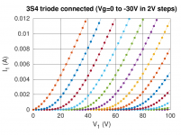
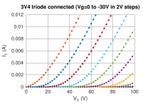
3S4 and 3V4 curves (triode connected)
I ran the 3S4 and 3V4 tubes through my curve tracer. Holy cow, they are very linear! Yes, they are DHT...
Gain is 5x for the 3S4 and 6.7x for the 3V4. I also have some 3C4 on order, so let's see what the curve tracer says for these.
I ran the 3S4 and 3V4 tubes through my curve tracer. Holy cow, they are very linear! Yes, they are DHT...
Gain is 5x for the 3S4 and 6.7x for the 3V4. I also have some 3C4 on order, so let's see what the curve tracer says for these.
Attachments
Last edited:
They are all in the same class of linearity. Limited differences.
Regarding the DC-DC converter (+linear reg), I don't think the higher voltage is a good reason for it. People should always be cautious regardless of 50 or 150V.
The real reason is that it can be high performance. I know for certain that power supplies for scientific equipment built from AC/DC noisy SMPS (typically 150 mV ripple) can get down to 40 uV ripple after DC/DC + linear regs.
I remember the AC/DC was a TDK Lambda and the DC/DC + Linear regs. were by Vicor or something like that....
While you are at it, you may also want to look at 1G4, 1H4 and type 30, a step better in linearity. Another step and there are the VT67, 864, UX201A, RE074, RE144, UX226, WE101D ... 😀... Holy cow, they are very linear! Yes, they are DHT...
Yes, DHT galore... so we're back to this:
I'd personally be happy to run the VFET amp from one of these 100 year old babies. However, in order to make this an easy-peasy design that will work out well for rookies, it might be better to go for something a bit more down-to-earth.
What are your opinions?
What level of sweetness is desired?
Is it for people detected of mild/mid/high diabetic,
for general/normal/ average taste people,
or people with extreme sweet taste addiction😀
I'd personally be happy to run the VFET amp from one of these 100 year old babies. However, in order to make this an easy-peasy design that will work out well for rookies, it might be better to go for something a bit more down-to-earth.
What are your opinions?
Designwise the ECC88 cathode coupled amplifier is pretty hard to beat. Low enough distortion (so little worry of altering intended presentation too much), forgiving B+ and Ia and simpler heater supply. Please note that the design is by no means final, perhaps lower standing current on the IRF610 source follower is desired to reduce dissipation or other desired tweaks, better ask those who wants to build a tube FE. As stated before, I'll help as much as I can debugging the prototype but I did not enter the lottery so final measurement on output and listening impression is not possible.
By contrast, a regular single triode inverting stage will have H2 amount comparable to the SIT so will alter intended presentation due to cancellation or or addition of H2 depending on phase.
A small battery DHT stage may still be manageable inside the original VFET chassis, but my preference leans to an external chassis for a tube FE by connecting the input of the SIT ouput stage directly to the female RCA.
While you are at it, you may also want to look at 1G4, 1H4 and type 30, a step better in linearity. Another step and there are the VT67, 864, UX201A, RE074, RE144, UX226, WE101D ... 😀
All these tubes really need a lot of care from the mechanical isolation and filament supply point of view.
With the caveat above: 1G4, 1H4, 30 and V67 (which is the military version of type 30) I would not recommend any of those. They are the most delicate to run. Definitely not for rookies.
864 is a rare tube.
UX201a still fairly common but - although to a lower degree - does have the same microphony issues mentioned above and it's not really cheap at a typical price of $40-45each for truly NOS tubes.
The UX226 is also right below that point. Maybe the type 26, ST glass version of the 226 at $40 per pair might be an option for more experienced people but still needs care....
RE and WE tubes outrageously expensive for what they can offer. You might complete the entire amplifier for a pair of WE101A.....
What are your opinions?
I think you either go for the ECC88 or 3S4/3V4.
The ECC88 runs at higher supply voltage but is simpler because the heater supply can be just rectifier + big-enough-capacitor (with low ESR) + a small resistor to limit the surge when the tube is cold and presents very low resistance.
My personal opinion is: I would go for the DHP in triode connection. With a CCS load it will give 15-20V rms with low distortion with just 60-70V anode voltage. It only needs a good filament supply: both current and voltage regulation.
No need for input JFET follower. Only needs a follower after to achieve the desired plate load at any modulation level. This can be a low Crss (in the 1-5 pf range) mosfet of suitable ratings. Many good ones nowadays.....
The ECC88 I have it in almost any brand but has never been a tube I have used in a power amplifier except as a "support" tube to make an integrated amplifier. What I mean by support? I mean an input stage made of the ECC88 running at as low as possible anode voltage and directly coupled to another voltage gain stage to get the total gain right. It has to work as linearly as possible with negligible distortion respect to the rest.
I don't like this frame-grid tube driving a power tube although some datasheets propose its use as output tube class B for 1W power....
For me its best use is at low level signal, mainly line preamp.
The VFET solid state front end boards which include DC-DC converters and which exist today, don't have and don't need linear regulators. Their schematics are public domain and posted on the Forum, search terms Marauder and/or Dreadnought. They achieve acceptably low output noise through simple passive filtering with an (-80dB / decade) transfer function. Recall that the problem with SMPS is not 100 Hz mains ripple or any other low frequency noise. Instead it is noise at the switcher frequency (>40 kHz) and its harmonics. These are quite comfortably handled with passive elements and competent PCB layout.
Recall that the problem with SMPS is not 100 Hz mains ripple or any other low frequency noise. Instead it is noise at the switcher frequency (>40 kHz) and its harmonics. These are quite comfortably handled with passive elements and competent PCB layout.
Which one is cheaper? I suspect that if you want to achieve microvolts noise (not difficult with linear regs) with passive components you will need really good inductors. I doubt you can do that with resistors or cheap low value inductors.
But I leave this to you.....
Since I have been living with my completed VFET amp for the last few days, I can say that it really doesn't need any added sweetness from the front end. When I was envisioning a tube-based front end, I was thinking more in terms of liquidity and the sometimes less tangible benefits to harmonic structure and imaging that well designed and executed tube circuits can bring to an amp. I will prefer circuits that are very linear, as well as low noise.
To this end, I view all vacuum tube designs as having some inherent risk due to the higher voltage B+ that is generally required. This is manageable by competent amp builders. While the VFET amp has one feature, namely the SMPS power brick, that makes it easy to construct, I don't agree that all future versions and iterations of that amp be limited to circuit voltages less than 50V.
I think it is important to design around tube models that are fairly easily available. If some builders with to do some tube-rolling, that can be fun as well, and there are certainly pairs of NOS tubes that can cost as much or more than the VFET kit + chassis. That is if one simply must try those rare Amperex Bugleboys or the like.
More about possible designs...
When I first saw the extra front end boards being offered concurrently with the VFET amp kit, I was drawn to the 'Bulwark' front end in particular. This bears more than a passing resemblance to some older tube circuits. Yes, the diff pair needs to be inverted, as well as the polarities of the bipolar output stage. Mark J. mentioned the Threshold NS-10 as inspiration for this design, and Zen Mod has kindly derived a clone NS-10 schematic for our education.
One thing of interest is that the output stage of these circuits is not push-pull, but single-ended with a CCS load.
It might be poetic to see an old Threshold design come back around in tube hybrid form.
Another classic design that also comes to mind is the front end portion of the venerable Dynakit Stereo 70. This has been updated by a few aftermarket companies to work with an EF86 and 12AU7. I built a front end card supplied by SDS Labs using the EF86 and an ECC99. It sounds wonderful in my old ST-70.
Attachments

- Home
- Amplifiers
- Tubes / Valves
- Designing a vacuum tube front end card for the VFET DIY amp