This input stage design does a better job of supporting preamps with a lower max output signal. Which is exactly why I like it.
It's an idea, I posted something I already have in my sim archive. R2 can be increased to reduce gain. 🙂
I'll pitch in my help if the design is to meet a certain target, as is the circuit can drive bridged AB100 output stage 400W into 8 ohm with ~8Vpp input.
I'll pitch in my help if the design is to meet a certain target, as is the circuit can drive bridged AB100 output stage 400W into 8 ohm with ~8Vpp input.
Last edited:
Bulwark, Marauder, and Dreadnought also support preamps with a lower max output signal. By changing their NFB resistor ratio, you can increase their gain to whatever value you like.
Let's stick to the design targets in the first post for now. I set the gain target such that it will be similar to the standard VFET front end, and work well with most line-level sources out there.
The ECC88/6DJ8 is a nice tube. It's linear, has the balls to drive pretty much everything, and it's not difficult to find. However, it would needs a plate voltage of maybe 130 VDC to work well here (Vg = -2.5 V, Ia = 8 mA). Would this voltage be okay for rookies?
The ECC88/6DJ8 is a nice tube. It's linear, has the balls to drive pretty much everything, and it's not difficult to find. However, it would needs a plate voltage of maybe 130 VDC to work well here (Vg = -2.5 V, Ia = 8 mA). Would this voltage be okay for rookies?
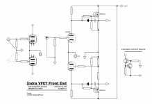
In this schematic, ECC88 will work just fine in A1 with B+ = 90V, Vak 45V, Vg = -1.25V and Ia = 2 mA. Please note revised R2 = 12k and R12 = 150r. Output voltage Vd = 10.48V rms at Input = 2V rms.
Ltspice asc and associated include file was zipped and attached to post #118. I did not enter the lottery hence can not properly test prototypes.
Code:
N-Period=1
Fourier components of V(d+)
DC component:0.00120064

Harmonic	Frequency	 Fourier 	Normalized	 Phase  	Normalized
 Number 	  [Hz]   	Component	 Component	[degree]	Phase [deg]
    1   	1.000e+03	4.000e+00	1.000e+00	   -0.05°	    0.00°
    2   	2.000e+03	1.464e-03	3.661e-04	  -90.02°	  -89.96°
    3   	3.000e+03	2.098e-05	5.246e-06	  176.08°	  176.14°
    4   	4.000e+03	2.244e-06	5.610e-07	   88.71°	   88.77°
    5   	5.000e+03	8.986e-08	2.246e-08	   -1.87°	   -1.81°
    6   	6.000e+03	2.421e-08	6.053e-09	   -7.83°	   -7.78°
    7   	7.000e+03	2.259e-08	5.647e-09	   -1.56°	   -1.51°
    8   	8.000e+03	1.945e-08	4.863e-09	   -0.00°	    0.05°
    9   	9.000e+03	1.634e-08	4.085e-09	   -0.48°	   -0.43°
Total Harmonic Distortion: 0.036614%(0.036614%)

N-Period=1
Fourier components of V(d-)
DC component:-0.00103231

Harmonic	Frequency	 Fourier 	Normalized	 Phase  	Normalized
 Number 	  [Hz]   	Component	 Component	[degree]	Phase [deg]
    1   	1.000e+03	4.001e+00	1.000e+00	  179.95°	    0.00°
    2   	2.000e+03	1.377e-03	3.442e-04	   89.46°	  -90.49°
    3   	3.000e+03	2.092e-05	5.228e-06	   -3.68°	 -183.63°
    4   	4.000e+03	2.178e-06	5.444e-07	  -91.72°	 -271.67°
    5   	5.000e+03	8.808e-08	2.201e-08	  178.15°	   -1.79°
    6   	6.000e+03	2.406e-08	6.013e-09	  171.57°	   -8.38°
    7   	7.000e+03	1.834e-08	4.583e-09	 -179.68°	 -359.63°
    8   	8.000e+03	1.594e-08	3.984e-09	 -179.39°	 -359.33°
    9   	9.000e+03	1.600e-08	3.998e-09	 -176.67°	 -356.61°
Total Harmonic Distortion: 0.034426%(0.034426%)Attachments

You might find the 3V4 is more linear, despite is a pentode in triode connection.The ECC88/6DJ8 is a nice tube. It's linear, has the balls to drive pretty much everything, and it's not difficult to find.
That's because it is filament type.
However, it would needs a plate voltage of maybe 130 VDC to work well here (Vg = -2.5 V, Ia = 8 mA). Would this voltage be okay for rookies?
It's ok. Same rules apply for 50, 100 and 150V....
In this schematic, ECC88...
I had trouble wrapping my head around your drawing so redrew it in a more conceptual manner. Could you check for errors please?
Why don’t you take full advatage of te CCS and derive the bottom tube input as shown in the snippet i’ve dropped on on the left?
dave
Attachments
Hi Dave,Why don’t you take full advatage of te CCS and derive the bottom tube input as shown in the snippet i’ve dropped on on the left?
I redraw the Rev1 schematic for you and hollow state folks, hopefully it becomes a bit more legible. 🙂
The circuit use R1 and R2 as feedback divider to adjust gain as desired. Short R2 if no feedback is desired to become as the snippet you made.
I think a source follower will perform better considering 90V B+, cathode follower should be doable with a 150V B+.
Attachments
Last edited:
I actually prefer the first set of schematics. They are quite readable and show the common cathode connection effectively.
I have been spending some time with my Sony VFET amp, and can say that it will require the very best performance from a new front end design in order to be worthy. And vacuum tubes sound better with a higher plate voltage. The 6DJ8 / ECC88 is a fine tube that has been used in some of the very best preamps. It needs what it needs. That indra1 has shown a promising design using only 150 Volts on the upper rail is actually quite remarkable. Many designs run this tube from voltages of 200V or higher.
In addition to a sufficient supply voltage, both the filament and plate supplies will need to be regulated separately for each channel. Again, this will be necessary to let the amplifier sound the very best that it is capable of. Power supply performance will make or break this front end as a viable option to compete with the simple and elegant one from Nelson Pass.
I have always considered the 6DJ8/6922/ECC88 to have a max plate voltage of 100 with optimal voltage of 90V . There are some variants that are spec'd for higher plate voltage but most are not.
http://www.tubebooks.org/tubedata/HB-3/Receiving-Type_Industrial_Tubes/6922.PDF
..dB
http://www.tubebooks.org/tubedata/HB-3/Receiving-Type_Industrial_Tubes/6922.PDF
..dB
Yes, that is why the 6DJ8 is well suited to this application. Supply voltages in the 120V to 150V range can allow for optimal plate voltage, depending on the load line (plate current) chosen.
I have always considered the 6DJ8/6922/ECC88 to have a max plate voltage of 100 with optimal voltage of 90V . There are some variants that are spec'd for higher plate voltage but most are not.
http://www.tubebooks.org/tubedata/HB-3/Receiving-Type_Industrial_Tubes/6922.PDF
..dB
Not true. All ECC88 variants (E88CC, PCC88, 6922 and 6DJ8) can take 220V max if plate dissipation is more than 0.8W and 250V if plate dissipation is kept equal to or less than 0.8W.
The main limiting factor is not the plate voltage but power dissipation. If one goes for 220V plate voltage (not to be confused with supply voltage...) the tube will be forced to work at lower plate current to stay within dissipation limits and might not behave as linear as at lower plate voltage with higher current. This was certainly true in the past where resistive plate loads were the standard. Nowadays, with active plate loads, one has a choice. For sure if the tube works at lower current it will have less mutual conductance and higher internal resistance but again this might or might not be an issue as is application dependent.
So the choice of the operative conditions is pretty much related to what one has in hand and what is needed. The higher plate voltage will allow larger output but will likely have a bit more distortion. Not a big difference in distortion if active plate loads are used. For sure there are better triodes for the latter application....the ECC88 is good, useful tube but not the ultimate triode for linearity.
12Vrms is not a big output in tube world so for this appliaction the ECC88 is good choice.
Last edited:
P.S.
The 130V limit in American datasheets was used with no limitation on plate dissipation up to the max rating but in reality it's better if dissipation is limited to 1W in any application. In such case higher voltage than 130V is possible...
For special quality tubes, restrictions were only applied for longer life service. Nothing to do with safety or faults.
Last edited:
In this schematic, ECC88 will work just fine in A1 with B+ = 90V, Vak 45V, Vg = -1.25V and Ia = 2 mA..
The design target asks for +/- 2 Vpk input voltage, so the grid needs to be biased lower than -2 V. As it is, your suggested bias point wouldn't work out. However, since the gain (33x) of the ECC88 is quite a bit higher than the target (about 7.5x), we might get away with adding some degeneration via the cathode resistor (i.e., without a bypassing capacitor), thereby reducing the headroom needed for the DC grid bias. I'd need to look into this a bit more.
I had trouble wrapping my head around your drawing so...
As far as I can tell, indras suggestion is just a long-tailed pair (LTP) with a CCS in the tail. I like LTPs as phase splitters, but I don't quite see the point here. We just need a single ended output from the front end to drive the VFET output stage.
It is preferable to have a circuit that drives both the D+ and D- outputs. This allows one to experience the effects of phase reversal in the front end vs output stage, if one is so inclined. Or even to drive a suitable chunk of iron 😉
I’m willing to build it and listen to it as the front end of my VFET amp. There is enough room in the rear of my amp for tube-based FE bards to take the place of Nelson’s with the Edcor.
There is still a lot of work ahead to design and build a power supply. It will need to be outboard in a separate chassis.
There is still a lot of work ahead to design and build a power supply. It will need to be outboard in a separate chassis.
- Home
- Amplifiers
- Tubes / Valves
- Designing a vacuum tube front end card for the VFET DIY amp