how can that work?
It can't 🙂 but that's not what you have drawn.
I seem to remember mentioning some weeks ago that you had to decide whether you wanted a true single rail design or a virtual ground arrangement running off a single supply. The two are subtly different.
So what you are describing is the second option, you have a virtual ground set up and so when you connect that to the main amp you are shorting the virtual ground to the battery negative... and that's why it doesn't work.
I think that is what you are saying. If so then you need to alter the preamp to operate as in the first option. Which is actually correct as drawn.
ok, the power supply with the zener would work.
i was so happy with that little device.
it s far away from being perfect, but my soldering skills got a bit better (on a scale from 1 to 10 it rose from 0 to 1.5) and it was my first project that worked at the first attempt.
now i have a new task and will get more practice.
your knowledge is so helpful!
thank you, mooly.
😀
The circuit you posted today is OK, the opamp generates a mid point reference (instead of the zener version). Keep your grounds as they are in todays picture and it will all work. You connect nothing signal related to the opamp output, it just provides the vref for the opamps in the circuit.
The circuit you posted today is OK, the opamp generates a mid point reference (instead of the zener version). Keep your grounds as they are in todays picture and it will all work. You connect nothing signal related to the opamp output, it just provides the vref for the opamps in the circuit.
It can't 🙂 but that's not what you have drawn.
....
you have a virtual ground set up and so when you connect that to the main amp you are shorting the virtual ground to the battery negative... and that's why it doesn't work.
The circuit you posted today is OK, the opamp generates a mid point reference (instead of the zener version). Keep your grounds as they are in todays picture and it will all work. You connect nothing signal related to the opamp output, it just provides the vref for the opamps in the circuit.
i don't get it.
i thought i built the circuit in the pic.
but i definitely shorted the battery and amplifier ground with the virtual ground for the opamps.
edit:
i think i got it now.
i connected the input (-) and output (-) of the preamp with the virtual ground.
but it should be connected with the battery ground.
right?
one thing is not as in the pic.
in this version i still use the volume pot of the amplifier.
should i put a 10k resistor between the preamp output + and - in this case?
Last edited:
Yes, input and output ground connect to the battery (its negative terminal). This is the audio ground in a single rail design. You connect nothing to the opamp "virtual ground". Just as you drew it in todays picture. Its all correct.
You can add a high value resistor from the preamp output (after the cap) to "ground" (which is the battery negative remember). And make sure that your input and output coupling caps are the correct way around. The "plus" on the cap goes to the preamp for both input and output caps, because these points are at half supply voltage.
You can add a high value resistor from the preamp output (after the cap) to "ground" (which is the battery negative remember). And make sure that your input and output coupling caps are the correct way around. The "plus" on the cap goes to the preamp for both input and output caps, because these points are at half supply voltage.
Ok, that works.
My pcb isnt beautiful any more, but it's ok.
On the input i have the cap's + facing input clamps.
I guess that's wrong.
Observation:
When i have the volume of my mp3 at max, the sound becomes weird.
Is that clipping?
Is that because of the gain in the summer or because of the polarity of the input caps or something else?
The sure way to get the polarity of any cap correct is to measure the voltage across it and fit accordingly. It does sound wrong as you have it. Check and correct that first.
The weird sound could be any one of the things you mention. You would need a scope to determine the actual levels from the MP3 player and then decide where the problem was. Also, some MP3 output stages (if they are headphone outputs) like to see a load of around 33 to say 47 ohms (like a headphone impedance) and that low resistor forms part of the Class D output filtering stage. Not all are like that, just some.
The weird sound could be any one of the things you mention. You would need a scope to determine the actual levels from the MP3 player and then decide where the problem was. Also, some MP3 output stages (if they are headphone outputs) like to see a load of around 33 to say 47 ohms (like a headphone impedance) and that low resistor forms part of the Class D output filtering stage. Not all are like that, just some.
MP3 output stages (if they are headphone outputs) like to see a load of around 33 to say 47 ohms
would that be the dc-resistance?
That would be the value of a suitable load resistor to use as a dummy load. Headphones present as a varying impedance, anywhere from the DC resistance of the coil (low) up to a hundred ohms or more depending on frequency.
too bad i didn't really test the previous versions on the same supply.
but this subsonic filter definitly does its job.
yesterday was a sweet sunny day.
i had 45 ltr br-box with me.
the sound was suprisingly good.
now that i know how it works i have to go back to the original project again.
but this subsonic filter definitly does its job.
yesterday was a sweet sunny day.
i had 45 ltr br-box with me.
the sound was suprisingly good.
now that i know how it works i have to go back to the original project again.
yes.
i used potentiometers like these:
25K OHM TRIMMER POTENTIOMETER CERMET 25 TURNS 3296W
i expected losses in sound quality compared to standard metal film resistors.
but i heard no difference.
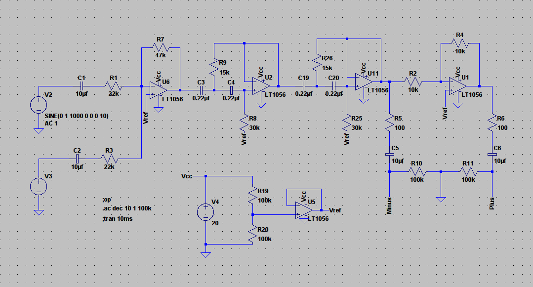
looking back at post 156, i wonder if i can differential output out of the posted circuit.
when i take one 'side' of the signal from u11 and the other side from u1.
add the series resistor, the series capacitor and 100k reference to ground to both sides.
would that do the job?
i used potentiometers like these:
25K OHM TRIMMER POTENTIOMETER CERMET 25 TURNS 3296W
i expected losses in sound quality compared to standard metal film resistors.
but i heard no difference.
looking back at post 156, i wonder if i can differential output out of the posted circuit.
when i take one 'side' of the signal from u11 and the other side from u1.
add the series resistor, the series capacitor and 100k reference to ground to both sides.
would that do the job?
Taking the signal from the opamp outputs as you describe would work OK if you want to feed the signal down a "balanced" cable... I'm not so sure you'll gain much though.
i have a tpa3123 class d amp board.
in the datasheet it looks like a perfect fit for my br-box when it is bridged.
but it can only be bridged with balanced input.
to i have to consider something related to the impendances of the outputs?
the circuit in post #156 has a ne5532 as u11 and a tl072 as u1.
do they have to be the same (both tl072)?
Many will probably disagree but no, they don't have to be the same, although it is usual for them to be so.
The really important part of the balanced impedance connection is the IMPEDANCE.
The 100r and the 100k and the 10uF should all be matched.
If possible the output impedance of the + & - opamps should also be the same. If there is a consistent difference in output impedance you can adjust the lower to match the higher by adding a low value resistor.
The voltages on the - & + outputs do not need to be the same.
The receiver reads the difference between the voltages and process that difference.
You can combine U6 & U2 by adopting an MFB 2pole active filter.
Except that D.Self tells us that a high pass MFB does not perform as well as a high pass unity gain S&K.
Low pass MFB is OK and it avoids the second opamp (less cost and less space).
Last edited:
- Status
- Not open for further replies.
- Home
- Source & Line
- Analog Line Level
- Designing a noob-preamp (single supply)