It depends totally on the power amp and its input circuitry. Its probably not a wise move.
If you really did only want only one cap in the chain then you have to measure the DC voltage on the power amp input circuitry (that's after its internal coupling cap) and then make sure the caps on your preamp output are polarised correctly to suit. You must also remove R10 and R11 because they would interfere with the biasing on the power amp.
My advice... don't even think about doing it.
AndrewT are aou saying that it should NOT cause problems to omit the input caps.
maybe i should add some more info:
my latest preamps (i build some just for fun) all had 22uF electros on their in and outputs.
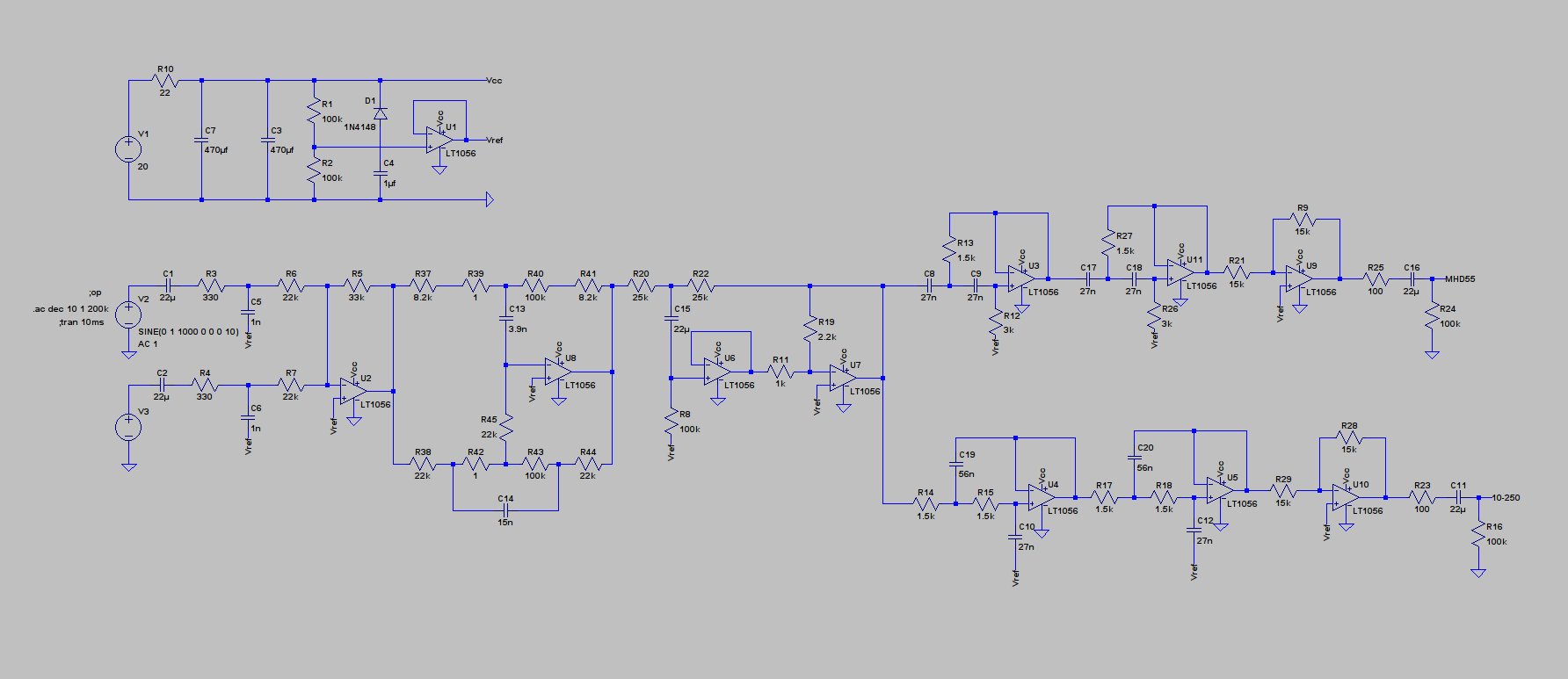
this is what i build this time:
the 1uF caps are on the TPA3116 class-d module.
they will go west either way, because i had sq improvements changing those against others on other already modded boards (those are chinese replicas of siemens epcos ....blabla).
...and now i have a small bunch of quite expensive 10uF polyprop caps, which i want to test.
maybe i should buid the preamp as usual with with the electros and just mod the class d module with the polyprops?
that would be a save way, but would say nothing about the sq of those new caps (i know there should be no big differences, but it's just fun doing it)
maybe i should add some more info:
my latest preamps (i build some just for fun) all had 22uF electros on their in and outputs.
this is what i build this time:
An externally hosted image should be here but it was not working when we last tested it.
the 1uF caps are on the TPA3116 class-d module.
they will go west either way, because i had sq improvements changing those against others on other already modded boards (those are chinese replicas of siemens epcos ....blabla).
...and now i have a small bunch of quite expensive 10uF polyprop caps, which i want to test.
maybe i should buid the preamp as usual with with the electros and just mod the class d module with the polyprops?
that would be a save way, but would say nothing about the sq of those new caps (i know there should be no big differences, but it's just fun doing it)
You have single polarity supplies and no bias voltage on the +IN, -IN pins.
No.AndrewT are aou saying that it should NOT cause problems to omit the input caps..................
I am saying you have omitted the biasing voltages on the inputs.
Do you know the differences between single supply circuits and dual polarity circuits?
The output to input coupling cap blocks DC voltages and couples AC signal voltages.
You need to block DC flowing from an output to an input.
Most equipment includes a DC blocking capacitor. The very few that don't generally use a DC servo to remove the damaging offset.
BUT,
once you have blocked the DC, you don't need to block it again, at that IN/OUT.
You need to block DC flowing from an output to an input.
Most equipment includes a DC blocking capacitor. The very few that don't generally use a DC servo to remove the damaging offset.
BUT,
once you have blocked the DC, you don't need to block it again, at that IN/OUT.
My newest setup has a new problem:
the preamp produces massive distortion audible from around 2500Hz up to higher frequencies.
I have tried different speakers and differnt power amps, so the problem must be in the preamp.
PSU is a sla battery.
this is i what built:
If somebody has an idea, please share it with me.
the preamp produces massive distortion audible from around 2500Hz up to higher frequencies.
I have tried different speakers and differnt power amps, so the problem must be in the preamp.
PSU is a sla battery.
this is i what built:
If somebody has an idea, please share it with me.
Last edited:
Does it work correctly in the simulation ? What opamps have you used ?
There have been a zillion posts since I last looked at this. I can't remember, do you have a scope to trace the signal.
There have been a zillion posts since I last looked at this. I can't remember, do you have a scope to trace the signal.
i have no scope.
i use tl071 in psu.
tl074 in the summer, tone control, master volume and filter.
tl072 in the output inverter.
it works super good besides that noise/distortion.
not in diagram are pots at each output.
i observe that the noise doesn't increase with turning up the master vol.
it becomes louder only with the pots at the outputs.
the noise is slightly audible at the woofer. (thats why i guess it starts around 2.5kHz. XO frequency is around 2.7kHz)
the 105db horn tweeter at the other output is not usable like this.
i switched to other speakers for the 'high' signal.
same noise there.
If you want to post the simulation file (the .asc) I can see if anything untoward shows up.
105 db horn tweeter... that is going to highlight signal to noise problems. As ever with anything like this, its difficult to imagine exactly what you are hearing. You should be designing for ultra low noise in this situation, that means different opamps such as the LM4562 (NE5532) and reducing impedances down to the lowest possible value by reducing resistor values by perhaps a factor of as much as 10 to 50 depending on the location. Caps need scaling up accordingly.
105 db horn tweeter... that is going to highlight signal to noise problems. As ever with anything like this, its difficult to imagine exactly what you are hearing. You should be designing for ultra low noise in this situation, that means different opamps such as the LM4562 (NE5532) and reducing impedances down to the lowest possible value by reducing resistor values by perhaps a factor of as much as 10 to 50 depending on the location. Caps need scaling up accordingly.
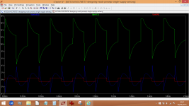
I've tried the sim and the stand out thing I notice is how much gain there is at around 4012Hz. The first image here shows the second opamp output vs the input signal. The second image was a squarewave test at the same frequency which shows clipping. The highly distorted waveform (which is 'normal' for high order filters) is the output of the final high pass section.
That massive gain could account for any odd 'shaped' noise you hear and at 4kHz its right at the most sensitive part of our hearing.
That massive gain could account for any odd 'shaped' noise you hear and at 4kHz its right at the most sensitive part of our hearing.
Attachments

That noise is created in filter section?
The choice of cap and resistor values is the reason for that?
I do not get it.
How do i get rid of that damn noise?
The choice of cap and resistor values is the reason for that?
I do not get it.
How do i get rid of that damn noise?
I'm no expert on filter design and their calculations but you certainly have a massive gain at that frequency in that second opamp stage. The noise created there although attenuated by the circuitry further on, has already been added into the mix.
As I say though, I'm not really the one to ask on filter design. All I can think of is that if that really is the filter response you want then you must look to minimise noise by choice of opamp and rescaling values as I mentioned earlier. Whether that would be enough though given your high efficiency speakers I wouldn't like to say.
As I say though, I'm not really the one to ask on filter design. All I can think of is that if that really is the filter response you want then you must look to minimise noise by choice of opamp and rescaling values as I mentioned earlier. Whether that would be enough though given your high efficiency speakers I wouldn't like to say.
before i soldered everything together i tested it on a breadboard.
i had the filters a little bit different:
2.2kHz xo point (2.7kHz soldered) and using 33nF / 68nF capacitors (27nF / 56nF soldered).
it uses tl074, too
i still have that filter on breadboard and connected it via jumper wires to the soldered rest of the stuff.
....et voilà!
it's much better!
i cannot believe that ittle adjusments in component values make such a difference.
maybe i did something wrong with the construction.
a noise is still there, but audible only at health-damaging levels.
i think i'll have to rebuild that section tommorow.
Well the gain is high above 4k as well if you look.
Just set the sim to 'AC Analysis' and look at the second opamp output and you will see a gain of 18db. That high gain means high noise, particularly with the resistor values used.
It also means that first stage is going to clip easily.
Just set the sim to 'AC Analysis' and look at the second opamp output and you will see a gain of 18db. That high gain means high noise, particularly with the resistor values used.
It also means that first stage is going to clip easily.
Attachments

What are the stages intended to do?
U2 is a gain stage that sums two channels.
The gain is 3times (33k/22k+33k/22k) equals +9.5dB
What does u8 do?
What does U6&7 do?
u3 & u11 are a cascaded unity gain B2 (=LR4) high pass filter
u4 & u5 are a cascaded unity gain B2 (=LR4) low pass filter
u9 does what?
u10 does what?
U2 is a gain stage that sums two channels.
The gain is 3times (33k/22k+33k/22k) equals +9.5dB
What does u8 do?
What does U6&7 do?
u3 & u11 are a cascaded unity gain B2 (=LR4) high pass filter
u4 & u5 are a cascaded unity gain B2 (=LR4) low pass filter
u9 does what?
u10 does what?
- Status
- Not open for further replies.
- Home
- Source & Line
- Analog Line Level
- Designing a noob-preamp (single supply)