The really important part of the balanced impedance connection is the IMPEDANCE.
It's worse than that Jim, if you go back a few posts you'll see the opamps are different types too. For an outdoor/indoor circuit like this there's no real problem though (imo 🙂 I mentioned some would disagree).
i'll try to achieve that, while keeping mooly's thoughts in mind.The really important part of the balanced impedance connection is the IMPEDANCE.
The 100r and the 100k and the 10uF should all be matched.
that will be the case.
but i guess that will not be enough to achieve the above.
If possible the output impedance of the + & - opamps should also be the same. If there is a consistent difference in output impedance you can adjust the lower to match the higher by adding a low value resistor.
i used 8pin-sockets which allow me to switch between different opamps.
i can easily change the 5532 for an tl072.
but i will try both when i have enough time.
when i have problems i'll come back to ask, because i don't think that matching the dc-resistance (which is all i can measure atm with my noob knowledge) would be enough.
The voltages on the - & + outputs do not need to be the same.
The receiver reads the difference between the voltages and process that difference.
that sounds easy.
but i need time to understand it in the context of balanced impendances.
You can combine U6 & U2 by adopting an MFB 2pole active filter.
Except that D.Self tells us that a high pass MFB does not perform as well as a high pass unity gain S&K.
Low pass MFB is OK and it avoids the second opamp (less cost and less space).
this actually is a high pass.
i have that (without the balanced thing) on a perf-board already.
it only needs a few changes.
i'm waiting for the weekend to come.....
usually we see a summing stage for a bass only speaker.
That then requires a low pass filter.
The MFB gives you a summing stage and a low pass filter in the one stage using one opamp.
This works really well.
I have used the MFB as a high pass filter. It seemed OK.
But D.Self says it is not as good as the unity gain S&K.
Your design with the separate summer and S&K filter fits with Self's recommendation.
The 100R should aim for better than +-0.1% of matching, not absolute value.
It does not matter if the 100r is actually 101.032 ohms as long as the other one matches it, i.e. somewhere between 100.93 and 101.13.
I have adopted Jensen's advice to use very large electro for source coupling. Try 100uF or 220uF.
A pair of 220uF back to back with a 1uF polypropylene acts like a very good 111uF coupling capacitor.
That then requires a low pass filter.
The MFB gives you a summing stage and a low pass filter in the one stage using one opamp.
This works really well.
I have used the MFB as a high pass filter. It seemed OK.
But D.Self says it is not as good as the unity gain S&K.
Your design with the separate summer and S&K filter fits with Self's recommendation.
Originally Posted by AndrewT View Post
The 100r and the 100k and the 10uF should all be matched.
the 100k and the 10uF will probably be OK at +-1%that will be the case.
but i guess that will not be enough to achieve the above.
The 100R should aim for better than +-0.1% of matching, not absolute value.
It does not matter if the 100r is actually 101.032 ohms as long as the other one matches it, i.e. somewhere between 100.93 and 101.13.
I have adopted Jensen's advice to use very large electro for source coupling. Try 100uF or 220uF.
A pair of 220uF back to back with a 1uF polypropylene acts like a very good 111uF coupling capacitor.
Last edited:
I have adopted Jensen's advice to use very large electro for source coupling. Try 100uF or 220uF.
A pair of 220uF back to back with a 1uF polypropylene acts like a very good 111uF coupling capacitor.
i'll try that in a next project.
i guess there need to be changes made wih the resistors, too?
I have adopted Jensen's advice to use very large electro for source coupling. Try 100uF or 220uF.
A pair of 220uF back to back with a 1uF polypropylene acts like a very good 111uF coupling capacitor.
i understand this not as good as i thought at the moment i read it.
i know how to calculate capacities (series, parallel), but switching to higher capacities doesn´t make sense to me.
why should i use higher capacities?
it works quite well so far with 10uF and 22k resistors (i have also tried 22uF and changed the resistors to 10k).
what else must come along with this change?
i´m doing a perf-board design for my next project.
is there a computer program for that?
doing it with a pen is quite fun.
but it isn´t after having almost everything finished and then wanting to change something in the layout.
Simply because Jensen say so..............why should i use higher capacities?
I suspect Jensen suggest the 220uF non polar to suit very low Receiver impedance.it works quite well so far with 10uF and 22k resistors (i have also tried 22uF and changed the resistors to 10k).
what else must come along with this change?
If you know that the Receiver impedance is much higher, then a lower value coupling cap can be used and it then enters the realm if not using an electro.
I have no idea. I do it long hand with pencil, paper and an eraser.i´m doing a perf-board design for my next project.
is there a computer program for that?
the balanced thing works!!
very nice to have!
with the tpa3123 i can now drive one single 8 ohmer to its max.
i have made a completely new prototype with a 24db hpf at ~35Hz, Q=0.7.
the variable filters are nice to determine the needed values.
now all spaekers get their own filters (and most of them their own amp).
my next project is a home subwoofer.
most of the construction plans i find for the woofer od my choice use a subwoofer-module with integrated lowpass and some kind of 'bass-extension' / 'bass-boost'.
i read somewhere that i can achieve that with a high or low Q filter.
can someone please point me towards a good source of information on that topic?
As a low pass the MFB has many advantages over both the unity gain S&K and the variable gain S&K (equal value component S&K).
D.Self explains why the MFB is not quite as good for high pass duty. Just as well I bought his filters book.
MFB, has gain that is independant of frequency and Q.
frequency and Q are set independantly.
is inverting and thus becomes a summing stage, simply by adding extra input resistors.
a big plus for s&k as a highpass is that with equal resistor design it is quite easy to produce a variable crossover with a stereo-potentiometer.
i'm going to try exactly that:
-mfb 18db high-pass with chebyshev-Q.
-variable 12db low-pass with butterworth-Q.
this is to imitate a subwoofer-modul (mivoc am80), which is used for a cabintet-design i want to build.
i'm on fire, because my last ltspice simulations and soldering actions all work well.
i'm still not sure about volume control.
i have some 'general' question.
the class d amps i use usually have A50K stereo pot connected to their inputs.
i still get the best results, when i use a 100K resistor (is this an attenuator?) at the outputs of my preamps.
1. i now remove the volume pot of the amp-board (A50K stereo)
2. wire the outputs of the preamp to a panel mount pot (A10K mono)
i still should use the 100K resistor?
are there any differences in the use of 10K pot instead of a 50K?
The resistance of the pot forms a frequency dependent filter, the characteristics of which depend on the input capacitance and resistance the wiper sees.
The 100k will almost certainly be altering the response... and there is nothing wrong in liking that 🙂
The 100k will almost certainly be altering the response... and there is nothing wrong in liking that 🙂
Hi everybody.
I have build a new subwoofer for my living room.
It plays very well when using it together with the battery-powered active crossovers that so far were subject of this thread.
but there is no chance any of my (our) creations work with a smps as the ps for the opamps is atm.
i would like to use the same 24V smps as the power amplifier uses.
the sound quality is much better when i use sla-batteries for the power amp, too.
But the batteries have their obvious dis advantages.
So my questions are:
Is it possible to use the same 24V-smps for both power amp and preamp?
How would that be done?
Is it worth (besides the fun of constructing it) to put effort into the design of a new ps, while i still could switch to two 9V batteries for he preamps?
I would also like to show you, what i have done in my last soldering actions.
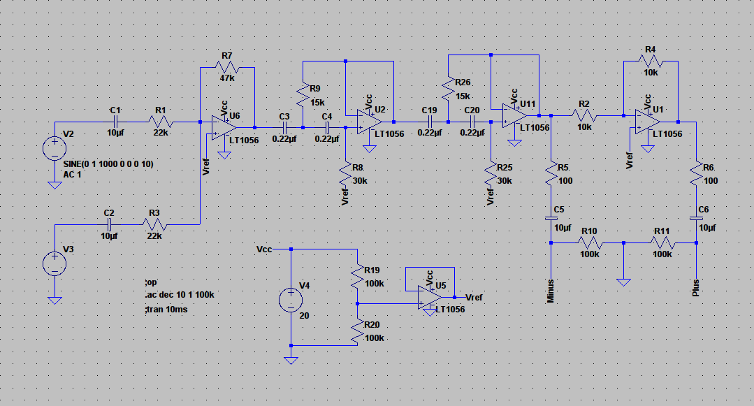
This circuit works as
- a 24db highpass with variable 'bass-extension' via R27 and R34, which represent a 50K stereo pot (variable Q),
- a 12db lowpass with variable crossover frequency via R28 and R29, which represent a 50K stereo pot, too.
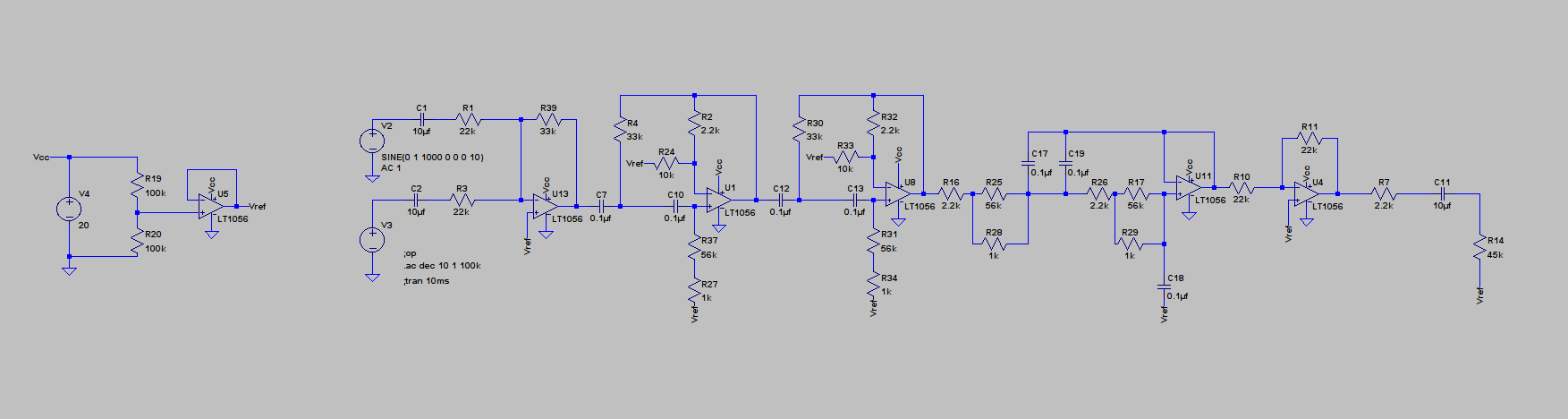
R27 & R34 = 1K
R28 & R29 = 1K
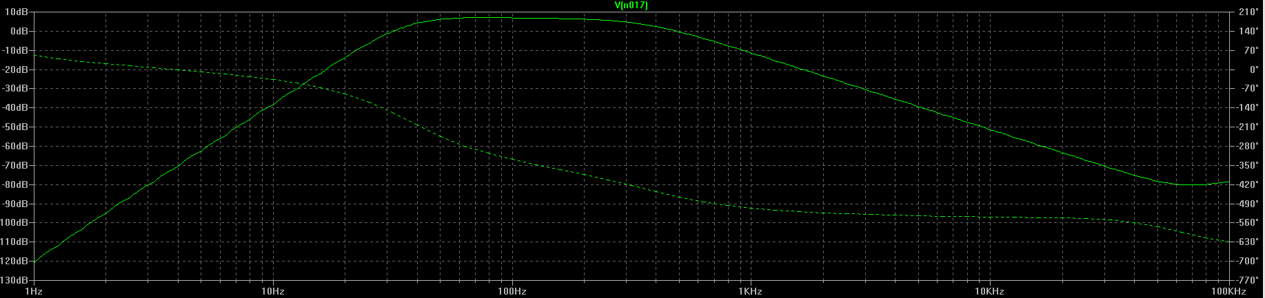
R27 & R34 = 45K
R28 & R29 = 1K
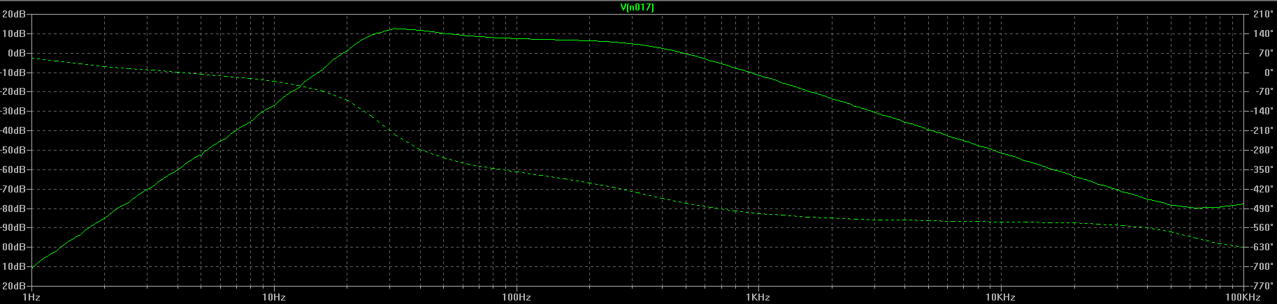
R27 & R34 = 45K
R28 & R29 = 35K
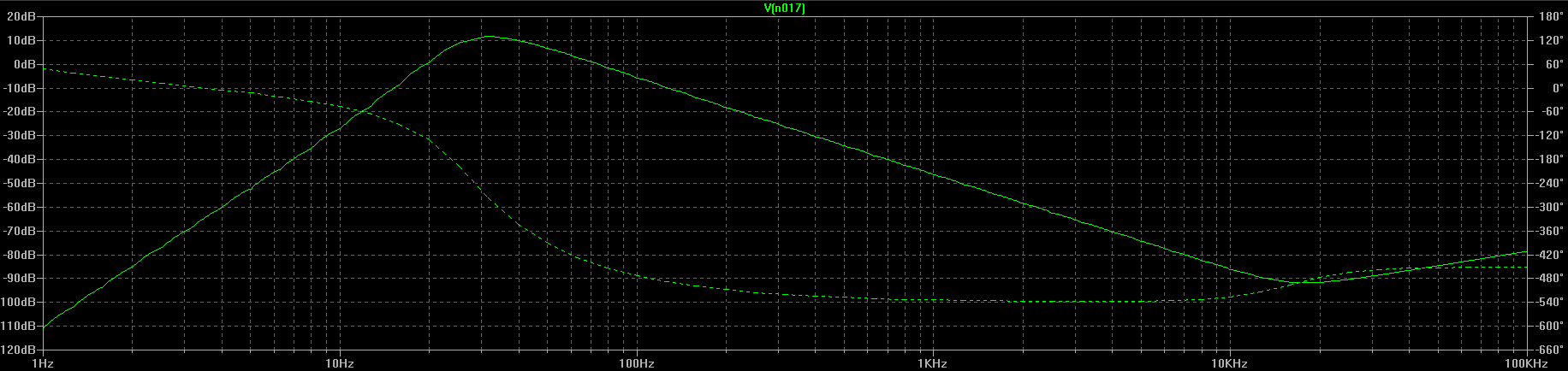
edit:
the resistor at the output should be 22K and 100K.
I have build a new subwoofer for my living room.
It plays very well when using it together with the battery-powered active crossovers that so far were subject of this thread.
but there is no chance any of my (our) creations work with a smps as the ps for the opamps is atm.
i would like to use the same 24V smps as the power amplifier uses.
the sound quality is much better when i use sla-batteries for the power amp, too.
But the batteries have their obvious dis advantages.
So my questions are:
Is it possible to use the same 24V-smps for both power amp and preamp?
How would that be done?
Is it worth (besides the fun of constructing it) to put effort into the design of a new ps, while i still could switch to two 9V batteries for he preamps?
I would also like to show you, what i have done in my last soldering actions.
This circuit works as
- a 24db highpass with variable 'bass-extension' via R27 and R34, which represent a 50K stereo pot (variable Q),
- a 12db lowpass with variable crossover frequency via R28 and R29, which represent a 50K stereo pot, too.
R27 & R34 = 1K
R28 & R29 = 1K
R27 & R34 = 45K
R28 & R29 = 1K
R27 & R34 = 45K
R28 & R29 = 35K
edit:
the resistor at the output should be 22K and 100K.
I've forgotten where all this was up too tbh.
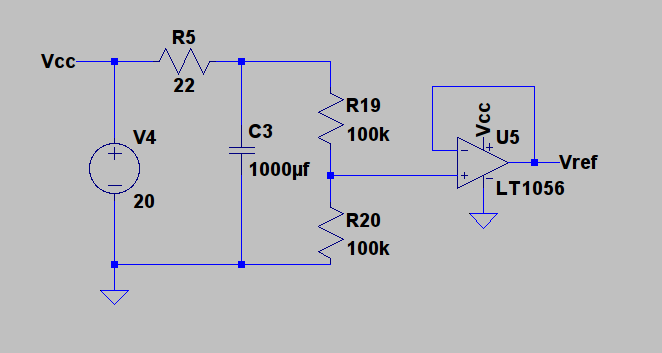
Running the opamp circuitry from 24 volts should present no problem but the opamp circuitry has to be configured as a single rail design (like the circuit you have attached). There is no problem doing that. Just make sure any caps are polarised correctly. You could usefully add a simple R/C filter to the power supply, say a 22 ohm and a 1000uf cap.
Running the opamp circuitry from 24 volts should present no problem but the opamp circuitry has to be configured as a single rail design (like the circuit you have attached). There is no problem doing that. Just make sure any caps are polarised correctly. You could usefully add a simple R/C filter to the power supply, say a 22 ohm and a 1000uf cap.
aha.
the problem is, that the smps delivers waves, that disturb the amplifiers in my preamp, right?
so the rc-filter should be a low pass, right?
now i'm not sure how to implement that.
would that work?
the problem is, that the smps delivers waves, that disturb the amplifiers in my preamp, right?
so the rc-filter should be a low pass, right?
now i'm not sure how to implement that.
would that work?
I'm sure that the point was to run the whole preamp circuit from the RC filtered supply, not just the reference voltage divider. 😉
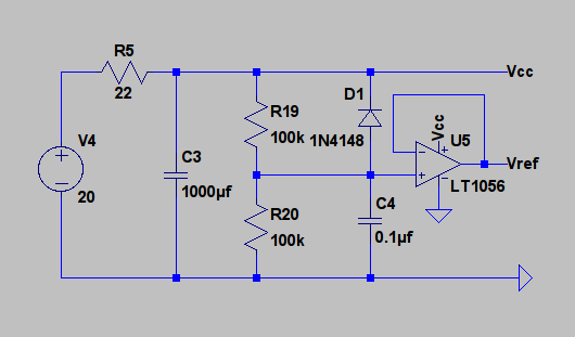
In addition, you should really give the lower 100k in the reference voltage divider a parallel capacitor (about 1µ-2.2µ in this case), otherwise the PSRR of the whole circuit will suck beyond belief. Which is pretty much the last thing you want when using a SMPS for power.
The upper 100k may need a reverse-biased small-signal diode (1N4148 etc.) in parallel to facilitate discharging upon power-down then, but if you don't get any cracking noises it'll probably be OK without.
i do not have all the parts and i didn't make it to the shop today.
what i have in my stock are several 100 Ohm resistors.
i'm going to take 4 of them in parallel for R5.
i do not have a 1000uF cap for C3.
but i have two 2200uF caps.
they should work with "minus" towards ground, right?
but shouldn't it work with their cathodes facing each other, too?
i have found a 1n4148 in an old radio which is a spare part source.
chances are a high it still works.
this should work for test.
one more question for my own understanding (and for choosing parts for next order):
what is the difference between the choice of
22R and 1000uF
and
10R and 2200uF
?
all current to supply the opamps has to flow through R5.
wouldn't a smaller resistor value for R5 cause less consumption?
on the other hand are bigger caps more expensive...
?
The value of R5 is a compromise between being to high and dropping to much voltage, and being to low and so not as effective. If you have 5 opamps and each draws 10 milliamps then a 22 ohm will drop 1.1 volts.
Don't be afraid of experimenting. You might find 50 ohms is OK with your opamps (it depends what type you used and how many). Providing its not cutting the supply down to much then higher is better as far as filtering goes.
A 2200 cap is fine too. You could also have this R-C filter followed by another one if you wanted. That would give even better filtering. No hard and fast rules... experiment.
And to make a bi-polar cap with two electrolytics then its either plus to plus or minus to minus. It doesn't matter which, but both caps must be identical. For a filtering/smoothing application though I would never recommend that as a first option. Use your 2200uf cap as they are.
if i have the outputs like in this....
is it save to omit input capacitors on the power amp?
i don´t see a reason to have them on the preamp-output and on the amp-input, too.
- Status
- Not open for further replies.
- Home
- Source & Line
- Analog Line Level
- Designing a noob-preamp (single supply)