Well I've read quite a bit and understood some.
One very important thing I saw and have always known is that the box should be inert for best results.
I am a luthier and have all the tools to easily make a ply or mdf construction but equally I renovate houses and find that it would take less time and be far more efficient to use compressed fibro in say 15mm thick sheets. The only bracing required in one of these would be to hold it together in the corners.
My particular application is a project to make a sound system on either side of a wall. The wall divides a pantry from a large living area.
I have a very nice pair of AMW bookshelf speakers that will be mounted at head height on a set of bookshelves constructed to accommodate all aspects of stereo and screen as well as books.
The bottom end I plan to mount in the pantry with the drivers set through the wall.
I have a pair of Falcon Acoustics replicas of the Kef B139 for this purpose.
To power the system I have a pair of Nelson Pass Aleph J amps that I built and love , and to crossover I have the DIY Biamp active crossover.
I have the luxury of a possible space of 900mm high by up to 1800mm wide and up to 600mm deep for each box.
But I just can't get my head around the science of the box dimensions.
I tried making an unfolded transmission line but there's no science and equally no great success. I listen to that at the moment along with a set of tiny bose top enders that give surprisingly good sound in my workshop.
But I know if I got those boxes right the bottom end could be quite stunning.
Has anyone got any basic dimensions that I could play with and has anyone made boxes from the previously mentioned compressed fibro? Obviously this is a material that needs to be installed and never moved again as it's the closest thing to concrete.
Otherwise I would consider using concrete as I think that could be the ultimate. If only I knew what those dimensions were?
For those unfamiliar, fibro is also known as asbestos cement. Often used in building construction for exterior walls, modern versions have been formulated without asbestos. The compressed variety is very heavy, and often available in 1/2" thicknesses and used for flooring.
If I remember correctly, dropping a hammer on this stuff reveals two aspects.. a lower frequency panel resonance as well as a higher frequency crash. Cement enclosures are often looked over for fear they will ring like a bell.
However a lot depends on what resonances are activated by the particular use of them. Further to this it might be possible that the excellent properties of some materials are not being properly exploited, or vice versa that only their weaknesses are.
It may seem reasonable that a massive (heavy) panel would be the way to go. Certainly, hardwood can seem like a good choice in some situations.. but then wood is better damped, which is an important factor. While mass can be hard to get moving, it's also hard to stop. Not right or wrong, but damping will reduce resonances.
The bottom end I plan to mount in the pantry with the drivers set through the wall.
I have a pair of Falcon Acoustics replicas of the Kef B139 for this purpose.
Matt (aka Scoot Joplin) did just that and reported it worked well. Do note the limited volume displacemet and the 1kHz renounce.
dave
... a lot depends on what resonances are activated by the particular use of them
It doesn’t matter whether concrete or not, where the box resonances are and whether the bandwidth of the device can excite them.
This means pushing the resonances way down in frequency or way up.
With the latter, in many cases you can push higher than the bandwidth, but also consider the low amount of continuous high frequency notes in real music, that at those frequencies energy to get a resonance going is greaty diminished and the wall material is much, much thicker relative to the wavelength. In practise this means getting high frequency, high Q (potential) resonances that are very unlikely to ever get excited. If you hit it with a hammer now that is different.
Moving the resonances down, what i call the BBC approach, is harder. In practise hard to get it out of the bandwidth that can be excited, but the BBC showe dresearch tha showed it less audiable (you can still hear it in things like the BC1 and the big Harbeths). Some people like it.
More mass pushed resonances down. Stiffness pushes them up. Shorter spans push them up (ie braces).
Concrete is tricky as it is heavy and stiff. An asset is that one can make much more complex walls with different thicknesses and damped cavities.
Usually a lot easier to build a box out of good plywood.
But, we are now entering a world, with 3D printing, where one can take the same concepts to new levels.
dave
A friend made a pizza oven outdoors of course, starting with a brick platform and then using a plywood frame he laid bricks over it in a semi cylindrical pattern and sealed it all with clay. The frame was later burned out.
At some stage they were partying and some bright spark put the ghetto blaster into the mouth of this oven to keep it out of the rain.
I haven't actually heard this but the report was that it became an awesome speaker that projected with great clarity and volume.
Therefore I'm considering a similar experiment as I need a pizza oven anyway, so maybe one that could take a front board made of fibro with a B139 mounted in it could show me whether that may be a good direction to follow.
I could easily make a brick enclosure in my pantry with a fibro front board.
So then the resonant frequency would become the important consideration.
My guitars generally resonate at about low F[on the guitar] preferably in between the properly tuned note when the pitch is A=440. So that's about 86Htz and it depends on the volume of the box, the stiffness of the body particularly the top, and the size of the soundhole. A thinner top with greater flexibility lowers the frequency.
So if that box were completely rigid the frequency could be as high as 220Htz and for every reduction of 5mm diameter of the soundhole it goes down by about 10Htz.
Irrelevant I know , sorry just thinking aloud.
OK so if I make a brick box that resonates down around 10Htz It should allow the B139 to do it's thing well?
I have one piece of info that says B139 works very well in 100litres. But no doubt baffles would be required and probably wadding as well.
Would unlined brick be troublesome for square waves? Perhaps compressed fibro would be easier and work better. Construction would certainly be easier. Any thoughts for which direction to consider?
You can get carried away in this direction and overlook other things like the cabinet shape and location.
Anyway, what are square waves in this situation, I'm thinking you meant standing waves, internal resonances. You will still need to consider and probably absorb sound within the box.
Anyway, what are square waves in this situation, I'm thinking you meant standing waves, internal resonances. You will still need to consider and probably absorb sound within the box.
and has anyone made boxes from the previously mentioned compressed fibro?
Had to look it up, but appears to be 'our' Durock, Denshield, HardieBacker, and WonderBoard, which I've used for outdoor speakers assembled with Locktite PL400, appropriate seam/joint tape. Driver installed with stainless hardware, gasket made from Nema 3R [rain tight] neoprene gasket.
OK I think I'll go for thick ply and baffles.
If it's going to be 100litres that could be [internally] 62.5cm high x 40cm x 40cm.
Not such a huge undertaking. But the way it's baffled is completely baffling, sorry.
Since it's a simple box for one driver maybe one simple baffle and a few heavy braces and then filled with poly wadding. Is there a scientific method to calculate these dimensions that anyone could suggest for a luddite?
I avoid 2 dimensions the same. 40=40.
A safe way to do the dimensions is such that the dimension ratios are irrational numbers. You will only ever get close, but that helps to avoid piling up side-to-side resonances.
historically i have like root[2] and root[3] (don’t use the former twice0, now i have an affection for the golden ratio.
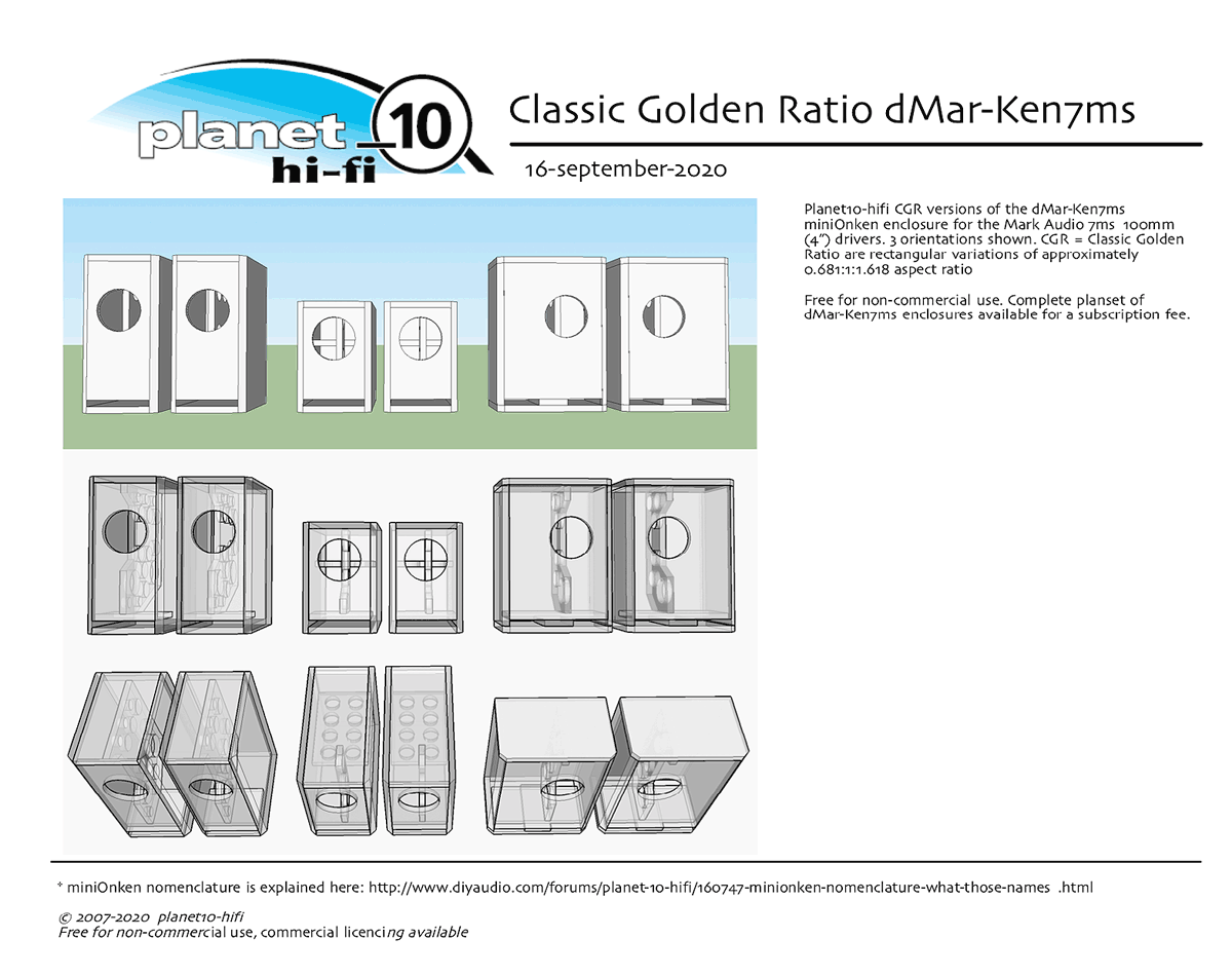
None are better than others.
dave
A safe way to do the dimensions is such that the dimension ratios are irrational numbers. You will only ever get close, but that helps to avoid piling up side-to-side resonances.
historically i have like root[2] and root[3] (don’t use the former twice0, now i have an affection for the golden ratio.
None are better than others.
dave
Hi, is it a bass box/sub woofer you are building Wot? 40cm dimension has first mode (standing wave) at about 425Hz which should be well above crossover frequency of a sub woofer and not a problem. Spreading out the dimensions like planet10 states spreads out the modes inside the box as well and this might be a good thing if the driver plays into the mid range. If the speaker plays into the mid range outside of the enclosure starts to matter as well since the shorter wavelengths start to diffract around the enclosure. Anyway, a lot more things to consider.
For a sub box, it makes sense to push the panel resonances as well as the standing waves inside high up above crossover frequency. This calls for small dimensions, stiff panels and ample bracing. The logic says a cube is best in this application, most volume, shortest dimensions, smallest panels. Of course there won't be too much difference (when box dimensions are small compared to wavelengths it produces) so build to dimensions that fits your space.
If it is a subwoofer you could skip the wadding if you wish. Wadding would turn some of the energy in standing waves inside the box into heat thus reducing the effect of said standing waves. Sub wavelengths are so long the wadding doesn't help much other than maybe help attenuate some noise from the driver motor if there is any and some distortion products higher in frequency. Not sure if these are audible anyway (with wadding or not). Wadding would affect the box Q a little, makes the box look like it is a bit bigger than it really is. Not sure if this is something you need to care about unless it is too small box for the driver.
Wanted to write a little since you were asking what goes into sizing a speaker enclosure.
Last edited:
I've had good results laminating cabinet walls using two even sheets and a thin layer of polyurethane adhesive. You could use a tile adhesive trowel to make it even. The polyurethane should feel a little like marshmallow. When you drop your hammer on a panel doesn't ring.
Thanks everyone, you have been most helpful. I've got a direction at last. Will report back with findings. Cheers.
Yes, as with resonances, if a dimension is “less” than the bandwidth it will not get excited.
dave
dave
I learned that with guitars as a continuous guitar side will resonate in the midrange so if we glue strips across the sides and divide that area into 6" lengths there is much less midrange possible, thus less cancellations, thus a net increase in the output of midrange is produced.
I know that is speaker box technology.
I know that is speaker box technology.
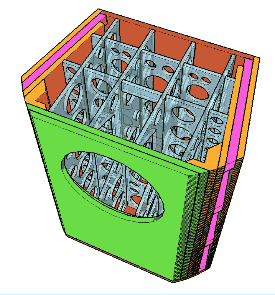
Do you mean loudspeaker box wall (panel) resonances? Bracing should divide the panels into higher aspect ratio pieces, which should "resonate less" than say a single large square panel. Different size and asymmetric "portions" would have different modes, which spread the problem across multiple frequencies. Similar idea as with the box dimensions. Other method could be to try concentrate the resonances up or down in frequency, out of pass band of the speaker. You could use strips along the panel instead of braces between two panels, but make them thick like I beams in construction. If I remember the strip should be about 5x the thicker than the panel.
These tricks only move the panel resonances around, shifts the frequency and severity (Q) but doesn't get rid of the resonances. One can possibly move the resonances out of the loudspeaker pass band like the in the sub woofer example I posted earlier. Damping would help get rid of the resonances, AllenB mentioned it already. Google should find plenty info on all of this.
These tricks only move the panel resonances around, shifts the frequency and severity (Q) but doesn't get rid of the resonances. One can possibly move the resonances out of the loudspeaker pass band like the in the sub woofer example I posted earlier. Damping would help get rid of the resonances, AllenB mentioned it already. Google should find plenty info on all of this.
Last edited:
You mean open back boxesI learned that with guitars as a continuous guitar side will resonate in the midrange so if we glue strips across the sides and divide that area into 6" lengths there is much less midrange possible, thus less cancellations, thus a net increase in the output of midrange is produced.
I know that is speaker box technology.
that is speaker box theory.
Technology is materials, shapes
Bracing can add resonances, if designed badly. If one uses circular type with holes too close together
Adding a brace to a panel takes the resonance of the original panel and makes it into 2 resonances at higher frequency. I prefer these to be different.
So yes, adding braces adds resonances. But ones that are higher in frequency (one brace on a panel will create 2 esonses at about 2x the frequency.
The point is to push the potential resonance high enuff in f®equency that they will not be exited.
In a multiWay this coule simply be above the bandwidth of the driver in that part of the box, or in a FR (or mid box) where one takes advantage of the lack of continuous energy sufficient enuff to get the panel to move.
So some experience and thot needs to be put into the brace design which in some cases are as much work as the rest of the box.
dave
I have the luxury of a possible space of 900mm high by up to 1800mm wide and up to 600mm deep for each box.
But I just can't get my head around the science of the box dimensions.
I tried making an unfolded transmission line but there's no science and equally no great success. I listen to that at the moment along with a set of tiny bose top enders that give surprisingly good sound in my workshop.
But I know if I got those boxes right the bottom end could be quite stunning.
Has anyone got any basic dimensions that I could play with......?
As a general rule we need from 4-10x Vas, so based on both these [Vas] specs you have enough: TL Links
With a 25 Hz Fs = Fp we need it to be ~34400/4/[25/0.81] = ~278.64 cm long.
Driver offset is normally [L*0.21] for max LF loading/~max 90 Hz XO point or [L*0.349] for a more extended usable bandwidth [BW]/~150 Hz XO point.
Your box = 972,000 cm^3/278.64 cm = ~3488.37 cm^2 pipe cross sectional area [CSA/width x depth]. Of course this will be less due to subtracting all the panel volumes, driver, so this calc was just to prove it's physically doable and perform well with minimal damping assuming a < ~150 Hz XO point.
If a higher one is desired, then more damping is required to flatten its 'ripple' with the trade-off of less bass output.
I'll leave it to you to figure out how to fold it to make it fit, but it's doable assuming the driver Fs, Vas specs are reasonably close.
Then damp [stuff] to 'taste' in the driver area. ;)
Thanks GM.
So square root of 3488.37 =approx 59 .
Are you saying overall it could be 59x59x278.64?
So as was said it's important to vary width and depth so perhaps it could be 65x53.5x278?
Thus the 278 folded in half is 139 . So I could fold the 53.5 on itself and end up with a height of 107.
So the overall box could be 139 long, 65 out from the wall and 107 high.
Am I understanding this correctly?
- Home
- Loudspeakers
- Multi-Way
- Design your own speaker from scratch discussion thread