Other way to think the graph
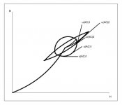
If you has a curve B=f(H), the derivative at each point represents the tangent to the curve at each point, as on each point
B = μ H
Then we can write
μ = dB/dH
OK, but in this case, why not to try using other form to the expression? Perhaps a second index in the formulae...
If I explain with words, my Tarzan-English will obscure even more.
Last option, DC bias plus two minor loops.
If it is indeed this, the two loops have the same incremental perm. they just represent different levels of excitation and one has substantially more hysteresis. As it is drawn the two loops also have different DC static DC points.
dave
OK, but in this case, why not to try using other form to the expression?
Because I can't change Classical Electrodynamics, as I been saying from post#1, due to magnetic anisotropy, magnetic permeability should be a tensor.
Derived equations comes from Maxwell's Equations, as they are Lorentz covariant, they can't change its form.
Perhaps a second index in the formulae...
No, that index makes reference to each transformer, 1 for transformer 1 and 2 for transformer 2.
Magnetic permeability is a continuous variable, and it is supposed to be a continuum medium.
For simplicity I avoided the use of a tensor for magnetic permeability, and now, because you don't understand a graph, must I reformulate the whole thread?
Not in your wildest dreams. 😀
If it is indeed this, the two loops have the same incremental perm. they just represent different levels of excitation and one has substantially more hysteresis. As it is drawn the two loops also have different DC static DC points.
dave
No, as I left perfectly clear, I use linear superposition principle, and divide the issue into three separate parts, one for DC field and another two for AC fields.
On that context, I have the freedom to put each coordinate system where I want.
Be in mind that physics does not depends on the coordinate system.
Putting the origin of coordinate system on the center of each loop would be the result of superposition, i.e. consider the three fields, DC and two AC simultaneously with a vectorial sum, maybe more clear, but very difficult to draw, and I am a bad draftsman.
If with "more hysteresis" you mean a bigger area inside the loop, was intended that the loop 1 has the bigger area, so more increasing "incremental permeability", then μ(AC)1 increases from too smaller values to too higher values, moreover, μ(AC)2 is quite constant over the curve.
It is said that a picture is worth a thousand words, mine are worth only a hundred! 😀
However, I hope this time you can understand. 😉
Edit: I forgot that both transformers has different Bdc, sorry, forget another graph. 🙄
Attachments
Last edited:
Tip#9 The air gap
The equation for the air gap
Gives us the TOTAL air gap, indeed there are core laminations with its air gap included, but for most standard cores, both EI or C, you MUST HALVED that calculated lG.
I've overlooked this little detail, one think that this is over understood, but not necessarily, sorry. 😱
Even more, the spacer in most cases must be even thinner than that, because the cut of the lamination is not perfect.
So, how to achieve the right value?
Let's suppose that Lp is the needed primary inductance, at a voltage U
Then, you can adjust the air gap to a current
U can be any voltage > 5 VRMS @ 50 Hz (or 60Hz), like Yvesm did on post#42
The equation for the air gap
lG = l (μ - μeff) / (μ μeff)
Gives us the TOTAL air gap, indeed there are core laminations with its air gap included, but for most standard cores, both EI or C, you MUST HALVED that calculated lG.
I've overlooked this little detail, one think that this is over understood, but not necessarily, sorry. 😱
Even more, the spacer in most cases must be even thinner than that, because the cut of the lamination is not perfect.
So, how to achieve the right value?
Let's suppose that Lp is the needed primary inductance, at a voltage U
U = i Zp = i √[Rp² + (2 π f Lp)²]
Then, you can adjust the air gap to a current
i = U / √[Rp² + (2 π f Lp)²]
U can be any voltage > 5 VRMS @ 50 Hz (or 60Hz), like Yvesm did on post#42
Last edited:
Due to continuity of normal component of B, it will not notice that dirty trick, but H will.
You will have a different magnetic permeability, its value will be in between of the two, analogous to the case of multiple dielectrics, the same with losses.
More precise details are very difficult to predict.
Hint: Make all calculations as if were te same lamination, after that adjust the air gap empirically, and in order to obtain a more or less homogeneous core, do the mix one by one, I mean one M6, one M50, and so on.
I did it with two unknown laminations, and it worked fine. 😉
I don't believe you are identifying the perms correctly.
each loop represents a complete cycle at a given frequency and the perm for that loop is the slope of the line drawn through the "tips" (points A-C in one of your illustrations) of the loop and you still have identical perms in both cases.
your points labeled u(AC)1 and u(AC)2 have no meaning in relation to the u of either minor loop for a given AC excitation. I know the effect you are trying to show but you are not presenting it properly and by your illustration, and methodology, you have a loop that goes from below the perm of air to that greater than infinite and that cannot happen.
In order to show the nonlinearity you are trying to show, you need to do multiple loops with different AC excitations and you will see the loops rotate in accordance to the rest of the parameters.
dave
I looked for corelosses in my Vacuumschmelze book and i found out that a small core (1,6kg) at 0,8T has 0,32W/kg loss and a much bigger core (4,91kg) at 0,4T has 0,088W/kg.
The bigger core has a bit less core loss and the advantage of lower copper losses.
The bigger core has a bit less core loss and the advantage of lower copper losses.
I don't believe you are identifying the perms correctly.
That I can't believe, is you are taking my drawings as if they were datasheets.

They are intended only to illustrate the point, and you are looking for the fifth paw of the cat (splitting hairs). 🙄
each loop represents a complete cycle at a given frequency and the perm for that loop is the slope of the line drawn through the "tips" (points A-C in one of your illustrations) of the loop
Totally agree, that is what I have been saying from many post so far, now you got it!
and you still have identical perms in both cases.
This is weird, is crystal clear to me, maybe I have a severe vision problem, I'm getting old, c'est la vie...
your points labeled u(AC)1 and u(AC)2 have no meaning in relation to the u of either minor loop for a given AC excitation. I know the effect you are trying to show but you are not presenting it properly and by your illustration, and methodology, you have a loop that goes from below the perm of air to that greater than infinite and that cannot happen.
Totally agree, the thicker loop is physically impossible, but is only intended to illustrate the point !!!

In order to show the nonlinearity you are trying to show, you need to do multiple loops with different AC excitations and you will see the loops rotate in accordance to the rest of the parameters.
dave
I can't make a decent drawing for barely two loops, you are asking for too much. 🙄
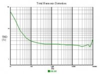
However, no need to do that, because maximum distortion is reached at the lowest frequency, so at the highest Bac, and that was precisely what I intended to draw.
I looked for corelosses in my Vacuumschmelze book and i found out that a small core (1,6kg) at 0,8T has 0,32W/kg loss and a much bigger core (4,91kg) at 0,4T has 0,088W/kg.
The bigger core has a bit less core loss and the advantage of lower copper losses.
Even supposing that your data correspond to the same lamination, thickness, etc. I wouldn't be so crazy to use barely 0.4 T, mind you that lamination "sees" the TOTAL field B, B(max)=Bac(max)+Bdc(max)
And even on that case
(0.8 T / 0.4 T)¹˙⁶ (1.6 Kg / 4.91 Kg) ≈ 0.99
Or if you prefer, trusting in your data
[(0.32 W/Kg) 1.6 Kg] / [(0.088 W/Kg) 4.91 Kg] ≈ 1.18
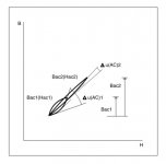
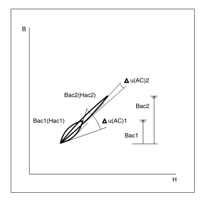
Both cores have almost the same hysteresis loss, so, the bigger one, has a loop with double thickness and almost the same area, again, the situation is quite similar, clearly
Δμ(AC)1 > Δμ(AC)2
And it is bigger by far, then μ(AC)2 is quite constant, μ(AC)1 doesn't.
WARNING !

The drawing below contents graphs that can be confusing for your understanding, they had been made using linear superposition principle, and coordinate systems had been placed arbitrarily, see it at your own risk.
Any resemblance to reality is not purely coincidental. 😀
Attachments
Last edited:
In this drawing U(AC)1 = U(AC)2 and there is no delta u(AC)1 or delta u(AC)2
dave
OK. Please prove it.
Thanks.
In this drawing U(AC)1 = U(AC)2 and there is no delta u(AC)1 or delta u(AC)2
dave
I don´t know why you say this. It is clear that the tangent to the loop Bac1 at the lower left corner has a less steeper slope than the tangent at the upper right corner, therefore the delta of the effective permeability can be seen to be greater on loop Bac1 than Bac2. (All this taking into account the inferior half of the loop)
As for if this is the case for a bigger core I don´t know but I´ll take popilins word for it. That graph is certainly well made to illustrate the point IMO.
you are looking for the fifth paw of the cat
El dicho no se traduce tan bien que digamos, limitemosnos a usarlo en castellano 😀
El dicho no se traduce tan bien que digamos, limitemosnos a usarlo en castellano 😀
Hi Marcelo
Thanks for your reply, words are not my thing, and my Tarzan-English doesn't help me so much. 😀
I hope not have said anything offensive, is just a saying with the supposed meaning at its side. 😱
Prove what?
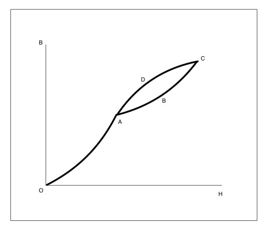
assuming what you show above is a magnetization curve (O-A) leading up to a minor loop (A-B-C-D) the following is correct.
The slope of a line drawn tangent to any point on the curve (O-A) represents permeability.
The slope of a line drawn through (A-C) represents the permeability of the minor loop (A-B-C-D)
I'm not sure what the slope of a line tangent to any point along the curve (A-B-C) or (C-D-A) tells other than possibly losses but it isn't the permeability.
dave
Why is not possible to find the fifth leg to the cat?
I think that is the more objective moral in this thread.
I think that is the more objective moral in this thread.
I don´t know why you say this. It is clear that the tangent to the loop Bac1 at the lower left corner has a less steeper slope than the tangent at the upper right corner, therefore the delta of the effective permeability can be seen to be greater on loop Bac1 than Bac2. (All this taking into account the inferior half of the loop)
As for if this is the case for a bigger core I don´t know but I´ll take popilins word for it. That graph is certainly well made to illustrate the point IMO.
El dicho no se traduce tan bien que digamos, limitemosnos a usarlo en castellano 😀
Hello,
The tangent to a point on a minor loop is not the permeability.

Here the two loops are labeled A-B-C-D and A-B2-C2-D2
The permeability of the minor loops is the slope of a line drawn through A-C and A-C2 and the slope of those two lines are the same hence the perm is the same.
Prove what?
assuming what you show above is a magnetization curve (O-A) leading up to a minor loop (A-B-C-D) the following is correct.
The slope of a line drawn tangent to any point on the curve (O-A) represents permeability.
The slope of a line drawn through (A-C) represents the permeability of the minor loop (A-B-C-D)
I'm not sure what the slope of a line tangent to any point along the curve (A-B-C) or (C-D-A) tells other than possibly losses but it isn't the permeability.
dave
"The incremental permeability uac of a material is the average permeability for an alternating magnetizing force ... (incremental permeability) is very nearly equal to the slope of a line connecting the tips of the hysteresis loop"
Electronics designer handbook, 1957
I stand corrected, as incremental permeability is defined as an average you are indeed right. But now I have a question, the incremental permeability is an average of what permeabilities? the tangents to the loop? This would make sense since the symmetry of the loop would make the average slope equal to the slope of line AC as you said. Therefore isn´t it valid to say that the permebility of the material is indeed varying constantly and we just use uac to simplify calculations?
Hello,
The tangent to a point on a minor loop is not the permeability.
Here the two loops are labeled A-B-C-D and A-B2-C2-D2
The permeability of the minor loops is the slope of a line drawn through A-C and A-C2 and the slope of those two lines are the same hence the perm is the same.
Sorry, I was writing a reply at the same time as you and didn´t see your reply. I undestood your point on incremental permeability, but please read my new doubts in the above post.
I guess the question to ask is lets assume the Loop A-B-C-D is for a 20hz sinewave. Now add in an additional sinewave of 2000hz and imagine 100 minor loops traversing the major loop A-B-C-D.
Will the slope of these minor loops remain the same or rotate?
dave
Will the slope of these minor loops remain the same or rotate?
dave
Prove what?
assuming what you show above is a magnetization curve (O-A) leading up to a minor loop (A-B-C-D) the following is correct.
I'm afraid that not all is correct.
The slope of a line drawn tangent to any point on the curve (O-A) represents permeability.
This is correct.

The slope of a line drawn through (A-C) represents the permeability of the minor loop (A-B-C-D)
Sorry, but this is totally wrong.
Let me explain, as I said before, if the medium is homogeneous and isotropic, is valid the relation
B = μ H
Ferromagnetic materials are highly anisotropic, due this magnetic anisotropy, μ is not a scalar anymore, but a tensor, because of that we have certain apprehension with tensors, we can take single values for μ at each point on the curve B=f(H), and each of those single values of μ can be think as the slope of straight line, the tangent to the curve at each point, as
μ = dB/dH
In few words, you are saying that magnetic permeability, AKA μ, is the slope of the straight line A-C, so you are denying magnetic anisotropy, and supposing μ=Constant, that is totally wrong, regardless of any book in this world can say in this respect.
μ is a continuous variable, not a constant, maybe we can have problems at the ends, but this is another story.
I'm not sure what the slope of a line tangent to any point along the curve (A-B-C) or (C-D-A) tells other than possibly losses but it isn't the permeability.
dave
Are you kidding ? What else ?
Hysteresis losses are related with
∫B.H
So the area inside the loop represents hysteresis losses, and the tangent of the curve at each point is called magnetic permeability, AKA μ.
Note: I can't draw the two loops with different inclinations, because my old Tango PCB works on 45º angles, however this is irrelevant, but mind you that, as I said before, coordinate systems are placed arbitrarily, you can rotate which you want, if it makes you happy.
Last edited:
- Status
- Not open for further replies.
- Home
- Amplifiers
- Tubes / Valves
- Design of transformers for valve amplifiers