
It appears that the two of you have reached a deadlock again, surprise...
Yes because he wants to play with words and doesn't have any experience!
My points are pretty simple:
1) Bdc for standard M6 (or unknown average M6) in not correct for the transformer EL156 was asking for because calculated using the wrong specs. The effective mu for that example is 330-350, depending on the actual gap, not 481. That is for standard unspecified M6.
2) AC effective permeability is not constant as function of
AC flux and this is reflected into the inductance. There is quite some variation initially up to a point where a max is reached and then it will slowly start to decrease. How much will decrease is a very practical thing!!! The real nominal value to use for calculations not only depends on the material but also on the actual treatment and finish! Can the gap can really be considered single valued? No, most of the times and depends on the quality of the laminations and their cut and how well it is implemented into the transformer!! That's why I don't suppose that mu AC is constant up to saturation. What is the best way to limit this issue? Answer: not to use high induction.
As in SE transformers one L is already limited one wants at least try to maximize it. I simply base my considerations on practical numbers and average construction not those derived from an unspecified THEORICAL curves.
3) Working at lower B also reduces core losses.
Last edited:
 45 will be taking a break from this (and other) threads for a couple of weeks.
The article from Partridge are also very useful:
http://www.audiofaidate.org/it/articoli/Partridge_disttrafcores_4.pdf
more of this:http://varietyofsound.wordpress.com/2012/03/30/distortion-in-transformer-cores-n-partridge-1939/
http://www.audiofaidate.org/it/articoli/Partridge_disttrafcores_4.pdf
more of this:http://varietyofsound.wordpress.com/2012/03/30/distortion-in-transformer-cores-n-partridge-1939/
Hi SY
Here the disappeared images of post #203, in order, I lost the whole Sunday making them with data processing included, if you can do something.
Thanks in advance.
Very Good !The article from Partridge are also very useful:
http://www.audiofaidate.org/it/articoli/Partridge_disttrafcores_4.pdf
Some abstract appears in RDH4 too, be aware of the units (lines of flux per square inch 😡)
Yves.
There was so much noise in the back-and-forth between the two, I would appreciate a concise summary from those that're more familiar with OPT design, on what popilin has presented, particularly if anything new or worthy has been revealed.
It appears that the two of you have reached a deadlock again, surprise...
popilin - could you please just summarize what is new or different with your equations (if any) vis-a-vis the "old" equations. You have posted so much stuff, so a short summary statement would be very helpful.
There was so much noise in the back-and-forth between the two, I would appreciate a concise summary from those that're more familiar with OPT design, on what popilin has presented, particularly if anything new or worthy has been revealed.
On post#2 there is a concise summary with all equations you need to make a transformer. 😉
You didn't read too much of the thread, right? 🙄
be aware of the units (lines of flux per square inch 😡)
Reminds me a comment of our Wavebourn 😀
http://www.diyaudio.com/forums/loun...rrors-technical-documents-15.html#post3098420
But could be worse, could be mks units, a real nightmare to use in electromagnetism, even Maxwell's equations changes its form, c does not appear anymore, and electromagnetic waves are less evident. 🙄
The article from Partridge are also very useful:
http://www.audiofaidate.org/it/articoli/Partridge_disttrafcores_4.pdf
more of this:distortion in transformer cores, N. Partridge, 1939 ? Variety Of Sound
Thanks Martin, very interesting articles!
From the beginning, go to the root of the problem i.e. magnetizing current, and after an approach focusing on Lp, seems to me that was the inspiration for the article on post#146
Note that in Fig.26 the plot of Lp (μ) vs B is almost constant with an air gap.
Ahh, what a moron, just now I realize that this plot is the proof that I need...sorry, I think slowly... 😀
Thank you very much! 🙂
It is not much ethical reply to a member into Sin Bin, however this thread is intended to give correct information about transformers, so correcting mistakes is a must, and it is not against forum rules. AFAIK
Both sentences are equivalents, to achieve that condition you must maximize Lp.
Almost all your analysis is based on a wrong supposition, i.e. the requisite that must be achieved the condition
2 π f Lp >> Req
NO you don't understand as you wrote yourself. The idea is MAXIMIZE Lp, MINIMIZE distorton.
Both sentences are equivalents, to achieve that condition you must maximize Lp.
Yes because he wants to play with words and doesn't have any experience!
I am unable to play with words, on the contrary, they play with me, Tarzan-English is not an advantage here, and it is not about experience, but physical facts.
1) Bdc for standard M6 (or unknown average M6) in not correct for the transformer EL156 was asking for because calculated using the wrong specs. The effective mu for that example is 330-350, depending on the actual gap, not 481. That is for standard unspecified M6.
As I said before Bac(max) and Bdc(max) depends on a design choice, based on estimates, for each particular case, for each particular core, and for each particular lamination, they are not fixed neither universal values, they are not calculated.
µeff is not a capricious value, neither a random number, it depends on previous choice of Bdc(max)
μeff = Bdc(max) (9 l) / [4 π Np i(DC)]
No need to put random numbers here, e.g. 330-350.
And is the other way around, with this calculated µeff, now you can calculate the air gap
lG = l (μ - μeff) / (μ μeff)
As GOSS have been improved over the years in terms of saturation and losses, its very high permeability is quite similar, so if you have the core datasheet better, but if not, an astoundingly good estimate can be made with almost any similar standard datasheet.
In the particular case of transformer of post#71 I used the data from Edcor M6 GOSS lamination, as permeability has a maximum in the region between 10 KGauss-12 KGauss, and the curve μ=f(B) is almost symetrical in that region, I took the value for B=16 KGauss because I needed μ at 6500 Gauss.
So with that value, μ=47000 @ 16000 Gauss, I obtained lG≈0.35 mm
Let suppose now a "Standard Unspecified M6" with μ=80000 @ unspecified B value, I would obtained lG≈0.36 mm, not too much difference, a so experienced winder would know it.
2) AC effective permeability is not constant as function of
AC flux and this is reflected into the inductance. There is quite some variation initially up to a point where a max is reached and then it will slowly start to decrease. How much will decrease is a very practical thing!!! The real nominal value to use for calculations not only depends on the material but also on the actual treatment and finish!
No, you are still confused, let me explain
As have been perfectly cleared on the first post, magnetic anisotropy makes extremely difficult to obtain the values of magnetic permeability for a given hysteresis curve, so we must work with DC values, such curves are in datasheets, like this, made with data from here
http://www.nssmc.com/product/catalog_download/pdf/D004je.pdf
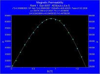
If we add an air gap, things are completely different, we have not μ anymore, but μeff, that is between one to two orders of magnitude lower, and above certain value of B, it is quite constant almost up to saturation, like this, which is constant at about 1% from 100 Gauss up to saturation!!!
Linearity comes from line, if the medium were homogeneous and isotropic, the relation between B and H would be linear too
B = μ H
Unfortunately, the core nightmare is a reality, but not all is lost, if we have a superposition of two fields, DC and AC, we can apply linear superposition principle, then we have something like this
With a careful design, you can make hysteresis loss very small, so the area into the curve B=f(H) will be also very small, as μ(AC) is the slope of the curve, it can be almost constant, that's the goal for linearity.
Then, for properly designed Single-Ended OPTs, μ(AC) is quite constant under all its normal operation.
Can the gap can really be considered single valued? No, most of the times and depends on the quality of the laminations and their cut and how well it is implemented into the transformer!!
In order to avoid such kind of problems, you can use C cores, the cut is amazingly accurate, if you use EI, usually the air gap is outside the transformer, so put the core over a glass (mostly plain) to align all laminations, practical and easy.
BTW. For calculation purposes, always you can consider the gap as single valued, except you need another strange property for your transformer.
That's why I don't suppose that mu AC is constant up to saturation. What is the best way to limit this issue? Answer: not to use high induction.
Wrong answer, that way μ(AC) will be in the region on it is even quite more constant.
As in SE transformers one L is already limited one wants at least try to maximize it. I simply base my considerations on practical numbers and average construction not those derived from an unspecified THEORICAL curves.
No, the root of your confusion lies on your design approach, let me explain
To lower distortion, your goal is to increase primary inductance
Lp = (4 π μ S Np²) / (9 l x 10⁸)
Three ways to do that
1- Increasing μ
2- Increasing Np
3- Increasing S
Has been shown that you almost can not increase μ, because of your obsession to obtain astoundingly low copper losses, you resign to use many turns, so Np is kept low, as it is squared, you must increase sky high S, because of l, you must increase S even more!
Then enormous cores are needed, even when you work with lower values of B, hysteresis losses deppends mostly on how big is your core, mind you that hysteresis losses are expressed in W/Kg and EI cores has higher losses, then the B=f(H) curve has a bigger area inside it, and with lower B the curve is even thicker.
Bingo! You did it! You increased μ, but now it is not quite constant anymore, you ruined linearity!!!
Is a valid approach increase Lp in order to decrease distortion, but must be do in the right way, your particular way to maximize Lp is the recipe to disaster in terms of linearity.
3) Working at lower B also reduces core losses.
Not necessarily
Bac(max) = (Uac x 10⁸) / (√2 π fo S Np)
Hysteresis loss
Wh ≈ η f (Bmax)¹˙⁶ x 10⁻⁸
Eddy current loss
We ≈ ξ d² f² (Bmax)² x 10⁻¹¹
B is a linear function on its parameters, core losses doesn't.
If you reduces B increasing Np, no problem, but if you increases S, the relation of S with the volume (weight) of the core is highly nonlinear, as you use enormous cores, you would achieve the paradox of reducing B with more core losses.
Attachments

On post#2 there is a concise summary with all equations you need to make a transformer. 😉
You didn't read too much of the thread, right? 🙄
Alright, I've been lazy, so now I will go back and read them.😀 more homework, urgh... so much to learn, so little time...
Late at night, tired and dizzy after struggling hours with mks units (I hate them) I can write almost anything. 😀
B is not a linear function on the sense
B = a x + b
I meant that its parameters varies linearly, that is! 😉
B is a linear function on its parameters
B is not a linear function on the sense
B = a x + b
I meant that its parameters varies linearly, that is! 😉
Let's consider again the transformer of post#71, why not use a bigger core?
OK, let's go for an EI 150 !
Uac = √(P Zp) = √(10 x 3000) ≈ 173 VRMS
For the same lamination, stacking factor is 0.95, so
S = 5 x 5 x 0.95 ≈ 23.75 cm²
l = 30 cm
Supposing now Bac=Bdc=4000 Gauss
Np = (Uac x 10⁸) / [√2 π fo S Bac(max)] ≈ 2049 (rounded to 2048)
Ns = Np √(η Zs / Zp) ≈ 101 (rounded to 102)
We have i(DC) = 80 mA, so
μeff = Bdc(max) (9 l) / [4 π Np i(DC)] ≈ 525
Lp = (4 π μ S Np²) / (9 l x 10⁸) ≈ 24 H
Supposing μ≈47000 we can estimate the air gap
lG = l (μ - μeff) / (μ μeff) ≈ 0.56 mm
Mean turn length, with correction for rounded corners is about
lm ≈ 278 mm
Then, for Φp=0.45 mm Φs=0.60 mm (trifilar)
Rp = ρ Np lm / (π rp²) ≈ 61 Ω
Rs = ρ Ns lm / (π rs²) ≈ 0.19 Ω
So
Ploss [%] = 100xRp/(Zp+Rp) ≈ 2 %
Sloss [%] = 100xRs/(Zs+Rs) ≈ 2.3 %
Insertion Loss ≈ 0.18 dB !!!
Suggested winding pattern (two primaries and three paralleded secondaries)
S-8P-S-8P-S
S = 102 turns
P = 128 turns
With 0.1 mm (NOMEX) between primary layrers, 0.56 mm (seven layers 0.08 mm NOMEX) between each primary and secondary windings, and another 0.56 mm to finish the bobbin
16x0.50+9x0.65+20x0.1+5x0.56 = 18.65 mm
Coil former has about 22 mm, so you must winding to 85% window, easy.
Leakage inductance
Ls = [0.417 Np² lm (2 n c + a)] / (10⁹ n² b) ≈ 10 mH
Leakage inductance increased a bit, but not to throw out the hairs.
Interwinding capacitance
C ≈ (ε A) / (4πd) ≈ 413 cm ≈ 460 pF
Interlayer capacitance
Cl ≈ (ε A) / (4πd) ≈ 2581 cm ≈ 2873 pF
Total winding capacitance
(Cw)⁻¹ ≈ (Cl)⁻¹ ∑ {(4/3nı) [1 - (1/nı)]}⁻¹ ı=1,...,NP
Cw ≈ 209 pF
Total distributed capacitance
Cd ≈ C ∑ (nı/N)² ı=1,...,m
Cd ≈ 663 pF
So shunt capacitance is
Cs = Cw + Cd ≈ 872 pF
Shunt capacitance was almost doubled, even increasing insulators, so winding pattern could be changed.
Hysteresis loss comparison
{[B(EI 150)] / [B(EI 84)]}¹˙⁶ [V(EI 150) / V(EI 84)] ≈ 0.39 * 5.23 ≈ 2
Then an EI 150 core has double hysteresis loss than an EI 84 core, even when B(max) was almost halved !
This is the most optimistic case, because modern lamination is better than on times of Steinmetz, and the exponent 1.6 would be reduced to at least 1.4
As I said before this could happen, even when Bac(max) was halved, bad news is that now, because double hysteresis loss with halved Bac(max), hysteresis loop is very thick, we don't have a quite constant μ(AC) anymore, we have destroyed linearity!!!
The moral is: Do not use big cores unnecessarily, if you really need a big core, E I cores are not the best option, go for a C core, unless you have the money for a more exotic material with lower losses.
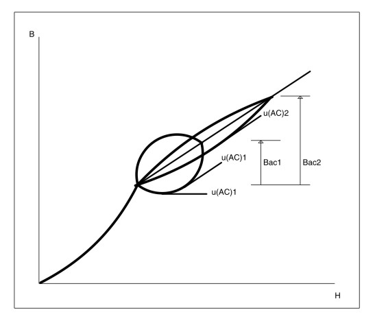
As now elementary math has abandoned us, due to magnetic anisotropy, we only can do a graphical description.
At each point on the B=f(H) curve, must be
Then μ(AC) is the "slope" of the curve at each point.

Bac1 and μ(AC)1 corresponds to transformer with EI 150 core, Bac2 and μ(AC)2 corresponds to humble transformer with EI 84 core.
A properly designed SE OPT, must have μ(AC) quite constant, so Lp must have the same behavior.
Huge variations on Lp, says us that linearity was destroyed.
However that has nothing to do with this variation
At rest voltage, about 1 mW @ 50 Hz, μ(AC) has a little bit lower value, above that, μ(AC) is quite constant almost up to saturation, and the gap will keep the working inductance to about 1.3 times the inductance of rest voltage.
Totally agree !!!
Totally agree !!!
At each point on the B=f(H) curve, must be
B = μ H
Then μ(AC) is the "slope" of the curve at each point.
Bac1 and μ(AC)1 corresponds to transformer with EI 150 core, Bac2 and μ(AC)2 corresponds to humble transformer with EI 84 core.
A properly designed SE OPT, must have μ(AC) quite constant, so Lp must have the same behavior.
Huge variations on Lp, says us that linearity was destroyed.
However that has nothing to do with this variation
And "dear" Popilin explain the data sheet below.
What does it mean that inductance is 20H at 1 mW and 26H nominal?
There is 30% increase! This is what you would call constant??
At rest voltage, about 1 mW @ 50 Hz, μ(AC) has a little bit lower value, above that, μ(AC) is quite constant almost up to saturation, and the gap will keep the working inductance to about 1.3 times the inductance of rest voltage.
Must I add that this almost always finishes with some "compromises" ?
Yves.
Totally agree !!!
It looks like you have to. For some that is not so obvious!😀
Totally agree !!!
Attachments

Last edited:
Hey, colifa! There are two µ(AC)1's in the diagram. Which is wrong?
There is one μ(AC)1 on each point of the curve1, as there are infinite points on the curve, so there are infinite μ(AC)1's on curve1, the same with curve2, the idea is to ilustrate that μ(AC)2 is quite constant over its curve, but μ(AC)1 varies a lot over its curve, even with halved Bac1, so linearity was broken. 😉
Let's clear that "colifa" means "a bit crazy guy" 🙄
That are friends! 😀
Last edited:
Let's clear that "colifa" means "a bit crazy guy" 🙄
😀
Also a totally crazy, like you! :-D
Hey,
I don't understand what this drawing is supposed to represent.
can you explain in words or label it better?
What is the line leading up to the two loops?
Are the loops minor loops with a DC bias?
dave
I don't understand what this drawing is supposed to represent.
can you explain in words or label it better?
What is the line leading up to the two loops?
Are the loops minor loops with a DC bias?
dave
Hey, colifa! There are two µ(AC)1's in the diagram. Which is wrong?
Other way to think the graph
If you has a curve B=f(H), the derivative at each point represents the tangent to the curve at each point, as on each point
B = μ H
Then we can write
μ = dB/dH
Maybe you can understand this way. 😉
Also a totally crazy, like you! :-D
Wow, thank you!

Don't help me so much... 🙄
Hey,
I don't understand what this drawing is supposed to represent.
can you explain in words or label it better?
What is the line leading up to the two loops?
Are the loops minor loops with a DC bias?
dave
If I explain with words, my Tarzan-English will obscure even more. 😀
Last option, DC bias plus two minor loops.
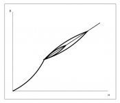
2- We have a superposition of two fields, DC and AC, we can apply linear superposition principle, then we have something like this

Bdc=f(Hdc) curve is from point O to A, Bac=f(Hac) curve is magnetic hysteresis loop, its path follows A-B-C-D-A points.
It results pretty clear that μ(AC) reaches a maximum at Bac(max).
If you do not like drawings, could be worse, could be tensor calculus...
- Status
- Not open for further replies.
- Home
- Amplifiers
- Tubes / Valves
- Design of transformers for valve amplifiers