Steff,
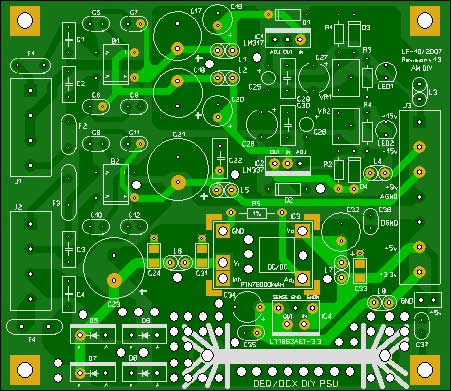
I see that there are two LEDs D5, D6 at the outputs, that appear to be wired in error (upside down). Don't know how they are placed on the board, but may be worthwhile to check.
They are not mentioned in the parts list at the bottom (there are other D5, D6's though that are rectifier diodes).
Jan Didden
janneman said:Steff,
I see that there are two LEDs D5, D6 at the outputs, that appear to be wired in error (upside down). Don't know how they are placed on the board, but may be worthwhile to check.
They are not mentioned in the parts list at the bottom (there are other D5, D6's though that are rectifier diodes).
Jan Didden
Right. Thanks. Still difficult for me with left and right. ;-)
Fine on the board.
.
Attachments
Has someone confirm if this board outputs the same voltage between the DCX2496 and the DEQ2496? I'm game to 2 sets of PCB they are the same.
😎
😎
Will said:Has someone confirm if this board outputs the same voltage between the DCX2496 and the DEQ2496? I'm game to 2 sets of PCB they are the same.
😎
oops sorry, what I meant was, I'm game for 2 sets of PCB if the DEQ and DCX both uses the same power supply arrangement.
The board should work with the DCX but no tested yet. I plan to do this saturday with a DCX's owner.
BUT, you will have to move the DSP board and use longer cable to fit the board inside the box.
.
BUT, you will have to move the DSP board and use longer cable to fit the board inside the box.
.
stef1777 said:The board should work with the DCX but no tested yet. I plan to do this saturday with a DCX's owner.
BUT, you will have to move the DSP board and use longer cable to fit the board inside the box.
.
Ok great, lets see how your testing works out to be.
I plan to make an outboard PSU altogether and link the DC supplies to the DCX/DEQ using umbilical cord , so size does not matter.
Ah yes as for your trafo needs why not check out this site:
http://eshop.diyclub.biz/product_info.php?cPath=152_74&products_id=55
the r-core trafo closes to this requirement is
R26-76 primary 115 X2 :0-16X2(1A)�A0-9(1A).
I just received this one yesterday, seems like a good deal.

Will said:
I plan to make an outboard PSU altogether and link the DC supplies to the DCX/DEQ using umbilical cord , so size does not matter.
You will generate loss and noise with the cable but you could try.
Will said:
R26-76 primary 115 X2 :0-16X2(1A)�A0-9(1A).
Values not good.
2 x 15v 15VA
2 x 7v 30VA (you can try with 6v but analog 9v will not may be work (LM7805 on the DEQ).
Others larger values will generate too more heat and some caps on the board will not accept this voltage.
stef1777 said:
You will generate loss and noise with the cable but you could try.
Another option is to only mount the trafo outboard, and bring AC into the DEQ/DCX using umbilical cord.
stef1777 said:
Values not good.
2 x 15v 15VA
2 x 7v 30VA (you can try with 6v but analog 9v will not may be work (LM7805 on the DEQ).
Others larger values will generate too more heat and some caps on the board will not accept this voltage.
I suppose the 16v power requirement should be ok right?
For the 0-9v section of the trafo, what about dropping the voltage using resistor to 7v? That might improve noise too.
Will said:
Another option is to only mount the trafo outboard, and bring AC into the DEQ/DCX using umbilical cord.
This is better, you can try. Add ferrite.
Will said:
I suppose the 16v power requirement should be ok right?
Will work but LM3xx will need heatsink and space is counted.
Will said:
For the 0-9v section of the trafo, what about dropping the voltage using resistor to 7v? That might improve noise too.
You have 1A for digital and 330mA for analog. Good luke!
If you replace bridge B2 with schottky (on a small add on board), you can may be use a 6v transformer for the analog "9v". To try.
.
Hi,
an outboard transformer should not cause a problem.
put the rectifier and first stage smoothing with the transformer.
V+,0,V- & lower V+,0,V- needs six wire umbilical. You might get away with 5 and use a 5pin XLR, by commoning the two 0v wires.
Put more local smoothing and the regulators inside the DCX.
Use the cables as the R of a CRC supply. The V+ & V- lines can be small gauge with 0r1 to 0r3 resistance to help remove some hum.
Keep the 0v line/s with low resistance.
With local smoothing and local regulation the DCX will perform well.
Moving the transformer outboard attenuates the magnetic and electrical fields at the circuit boards and the CRC attenuates the ripple on the supply, helping the regs and circuits to perform better. CRC also attenuates the HF rubbish that gets past the transformer.
Looks like a win win situation.
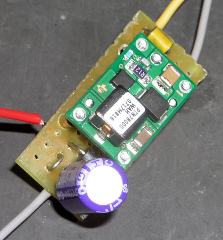
What do think to use an high end DC/DC converter to generate the digital 5v? Something with smooth PI filters at input and output.
We can reduce global heat by 75%. The 3.3v regulator will be connected to the digital 5v. The rest of the circuit will stay the same. Cost will be equivalent (no fan, only one heatsink -> spending will go to the DC/DC module). Only 3 CMS 1206 capacitors to solder (thrue hole version 10 times expensive). Same PCB size. More versatile input voltage.
.
Ryssen said:If that sucker 😉 doesn´t affect sound in a negative way,then go for it,I say.🙂
This is only for the digital part and for the important 3.3v, we still have the good LT1963. It's a 550Khz DC/DC with all protection features ready to use. The circuit wil be someting like this. Filter need more work to select the best inductor or ferrite. Transient response is a bit low. Regulation is ok.
Cost is 12€ w/o vat. At first time, I was looking to use a complete own design with a double DC/DC chip but cost is far more expensive if we source components ourself. And, it's a pain to solder...
.
Attachments
Adios Fan!!!
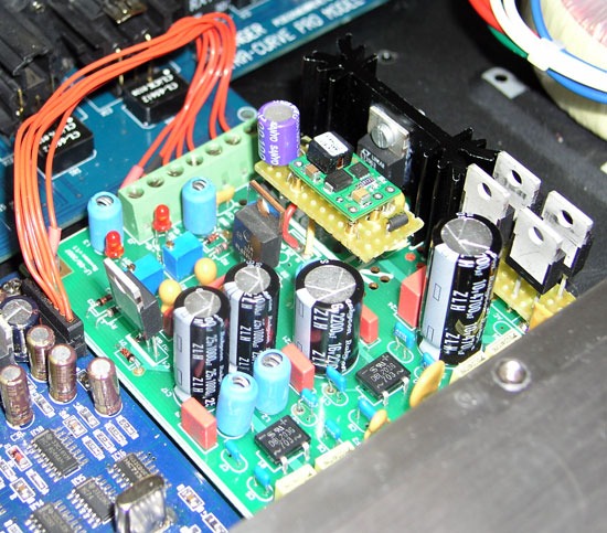
It seems to work fine with the DEQ. No problem at startup. I'm adjusting some caps (again) with this new circuit.
.
It seems to work fine with the DEQ. No problem at startup. I'm adjusting some caps (again) with this new circuit.
.
Good news everybody. The prototype work well inside the DCX2496 too. 🙂
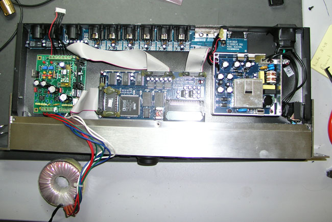
With the help of kepa1, we used a part of this Saturday afternoon to test the latest version of the prototype inside its DCX2496. Good surprise too, the temperature of the PSU is lower than using it with a DEQ. The 3.3v heatsink was around 32°C (42°C with the DEQ). The rest was close to be identical.
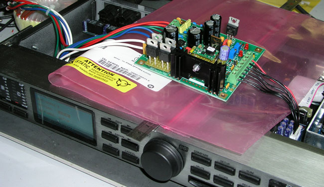
For the placement and for the one who want something easy to do, the best seems to place the PSU at the left of the DSP board, and the transformer can replace the original PSU. Or you can try the other way. 5 holes to drill only.
I will order a first batch of 20 custom transformers next week. For the the final PCB, I plan to have them for the end of the month. If all is fine, all these will be available the first days of November.
Have a nice week-end.
.
With the help of kepa1, we used a part of this Saturday afternoon to test the latest version of the prototype inside its DCX2496. Good surprise too, the temperature of the PSU is lower than using it with a DEQ. The 3.3v heatsink was around 32°C (42°C with the DEQ). The rest was close to be identical.
For the placement and for the one who want something easy to do, the best seems to place the PSU at the left of the DSP board, and the transformer can replace the original PSU. Or you can try the other way. 5 holes to drill only.
I will order a first batch of 20 custom transformers next week. For the the final PCB, I plan to have them for the end of the month. If all is fine, all these will be available the first days of November.
Have a nice week-end.
.
Wont the AC in the leads from the trafo disturb tha DSP card,if it runs near it?to place the PSU at the left of the DSP board, and the transformer can replace the original PSU.
I know well that's not the best but you can make a try. 
You can build 2 twisted cables, one with the 4 analog and another with the 4 digital. You shield them with an aluminum ribbon and add one or two ferrite bead. You do same with the DC cable. It can work, the distance is not so important.
On the front panel, inside, you have a large and thick aluminum line who will protect the cable going to the front panel from the dsp board.
You can also place an aluminum plate between the toroid and the dsp board. I've done this on my own DEQ. I used a side of the original psu.
The first is to have a shorter possible cable for DC signals.
But may be others will have another thinking!
.
- Home
- Amplifiers
- Power Supplies
- Dedicated PSU for DEQ/DCX2496