Hi,
Also note how Naim has cut slot's into the groundplane to ensure the elctrons behave themselves and only go where they are supposed to.
Naim is actually not a bad place to learn about layout. They always where pretty switched on.
I once serviced a pair of active speaker with pre-naim Julian Vererker electronics, in my days at MVE London, even then the layout was impressive.
I have never been the greatest fan of Naim's sound, but that they sounded comparatively SO GOOD while always using SO PEDESTRIAN circuitry is likely down to as a large degree to layout as it is to the powersupplies.
Ciao T
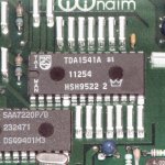
Eric - here is a typical Naim implementation:
An externally hosted image should be here but it was not working when we last tested it.
- It's not clear in my pic, but the caps return to a ground plane tied to the dac's own 0v plane.
Also note how Naim has cut slot's into the groundplane to ensure the elctrons behave themselves and only go where they are supposed to.
Naim is actually not a bad place to learn about layout. They always where pretty switched on.
I once serviced a pair of active speaker with pre-naim Julian Vererker electronics, in my days at MVE London, even then the layout was impressive.
I have never been the greatest fan of Naim's sound, but that they sounded comparatively SO GOOD while always using SO PEDESTRIAN circuitry is likely down to as a large degree to layout as it is to the powersupplies.
Ciao T
Decoupling TDA1541A S1 by NAIM AUDIO
Thanks Martin, thanks ThorstenL for those details.

I push contrast on the picture to see details.
Thanks Martin, thanks ThorstenL for those details.
Sure. I remember a preamplifier with wonderful 300VA transformer and tantalum capacitors in the signal pathI have never been the greatest fan of Naim's sound, but that they sounded comparatively SO GOOD while always using SO PEDESTRIAN circuitry is likely down to as a large degree to layout as it is to the powersupplies.
I push contrast on the picture to see details.
Attachments
I also played with those decoupling caps and currently have a rather weird setup but based on the idea that the decoupling caps might function better if accompanied by a snubber!!
Yes, well, it did seem promising back then, so I decided to try with the "fastest" (sorry) caps that I had that were Rifa styrene pfe216 (not the 225s), those big blue plastic case ones, and stood them on their ends (yes, long leads!) and added the snubbers of 1n47 + 0.165 (2 x 0.33 SMD in //) across each one (1n47 is also pfe216) and it works ridiculously well.
The decoupling cap range appears to be 125 -> 133nF (ended up at 128nF +/- 0.5nF) and with the standard 470pF cap on pins 16/17 reduced to 410pF Rifa Styrene pfe216, there didn't seem any difference and it was expected! (It could also be my less than rigorous scientific methods!)
And on pins 13/18 I also found that 4u7 is the "sweet-spot" for my old ears and ended up with the Mundorf Supreme (or Obbligato) which also has ridiculouly long leads.
Without having good clocks, DEM overdrive, best power supplies, I doubt that much technical significance can be attributed to my efforts, but it is rather curious that such outlandish disregard for accepted good engineering would work at all well.
The output stage for my much abused "ol' banger" is an upgraded clone of the original PassLabs D1 o/p stage, not the original IC stage in the player
For a reference, I do know the sound of both the big Zanden and the Abbington CD777 quite well.
Amazing, nearly 30 years after original design and many of us still prefer this rather basic digital circuit, altho I'm into the recent ESS Sabre dac now (Ackodac)
Incidently, could anyone advise if there are any of the NAIM based pcbs available for a new version of the 1541A dac (NOS) still available?
Everyone seems to have their own recipe without any adverse effects. I went with polycarbonate decoupling and the analogmetric dac produces noise when playing loud passages. Might be the clock or the cs8412.
Hi,
I think you need to tell us more than "polycarbonate decoupling", we may be able to help.
Ciao T
Everyone seems to have their own recipe without any adverse effects. I went with polycarbonate decoupling and the analogmetric dac produces noise when playing loud passages. Might be the clock or the cs8412.
I think you need to tell us more than "polycarbonate decoupling", we may be able to help.
Ciao T
Hi Thorsten, I used MKC 0.1uf but I don't think it causes any problem. On the contrary it sounds very good. Unfortunately there is some noise buildup/interference when the dac plays loud passages like if the sound was clipping badly.
Hi,
Do you have a schematic for the thing?
Ciao T
Hi Thorsten, I used MKC 0.1uf but I don't think it causes any problem. On the contrary it sounds very good. Unfortunately there is some noise buildup/interference when the dac plays loud passages like if the sound was clipping badly.
Do you have a schematic for the thing?
Ciao T
Ther is a whole wealth of information out there regarding decoupling capacitors and dogital lay out, it is not a misystery and it is not open to fanciful ideas. It is based on hard exidence and years of doing digital designs. I posted some links earlier regarding decoupling and how they work and how to implement it.
SLOTS in ground planes, dont do them, unless you realy know why you are putting them there, you can cause more problems than you solve, and even if there are slots on the ground on a top layer there may not be slots on inner ground planes. A contigous ground plane is best these days. So I would not reccomend trying to guess why someone at Naim has don what they have done, but reasearch and read stuff like Henry Ott, Electormagetic compatability Engineering; or stuff by Howard Johnson to name 2 of many sources, and look around at Engineering Based PCB froums.
SLOTS in ground planes, dont do them, unless you realy know why you are putting them there, you can cause more problems than you solve, and even if there are slots on the ground on a top layer there may not be slots on inner ground planes. A contigous ground plane is best these days. So I would not reccomend trying to guess why someone at Naim has don what they have done, but reasearch and read stuff like Henry Ott, Electormagetic compatability Engineering; or stuff by Howard Johnson to name 2 of many sources, and look around at Engineering Based PCB froums.
Here is the schematic picture.
An externally hosted image should be here but it was not working when we last tested it.
I'm surprised to see AD797 as I/V in a real-world design rather than in a manufacturer's datasheet 😀 Also IME, the 2n2 fb cap is way too high for decent sound. Try substituting an LM6171 for the AD797 and reducing the 2n2 to 10pF then tell us you hear no difference.😱
Hi,
This has the usual "reclocker" system (U1/X1) that just does not work at all, I hope you have removed it. You can later re-use U1 as divider for DEM reclocking if you like.
The wrong reclocking sounds like static at low levels and can sound like distortion at high levels.
The SPDIF Input circuit with the Transformer shown basically barely works.
If the output circuit is as shown and really has AD797 I suspect they are oscillating. In fact, for me AD797's always oscillate... ;-) Also, you do need the nominal supply line voltges for the Op-Amp as the circuit as shown produces significant (3.6V) DC offset, with normal dropout voltages etc. the Op-Amp's must run at least on +/- 12V.
Try something tame like OPA604 for starters, to make sure everything works okay.
The values of the Filter are also wrong for using the SAA7220, the analogue stage must use a precisely defined frequency response which is determined by the revision of the Filter (e.g. the SAA7220A has a different SAA7220C).
Ciao T
Here is the schematic picture.
Hello
There is another little detail, normally there is a 1K ohm .047 uf filter to be connect to pin 20 of the CS8412, but in your schematic they connected it to pin 19, so it it should be connect to pin 20 like in the image I include.
Bye
Gaetan
Attachments
Last edited:
Hi,
The wrong reclocking sounds like static at low levels and can sound like distortion at high levels.
The SPDIF Input circuit with the Transformer shown basically barely works.
Ciao T
Hi Thorsten. At low volume there isn't any static, but not much instrument separation. It's only when the music gets very charged that I hear scratching noise + clipping.
Thanks Gaetan for noticing this, I will correct that, as for the DEM relocking, Spdif and disconnecting the clock and SAA740 I am lost. 😕
Hi,
Do you have a PC with SPDIF output or a CD-Player and some test CD's, plus a 'scope (nothing fancy, 20MHz analogue 'scope should do, 60MHz or 100MHz is a Bonus)? I think you take some readings.
Best look at a generic Dac with CS8412 or CS8414 and I2S connection to the DAC (you can also look at the CS8412 datasheet, if you can work things out from there) and then remove the clock and the divider (4040).
For SPDIF, look at the CS8412/8414 Datasheet and use the simplest configuration given, remove the transformer (at least untill you have the tools and knowledge to correctly implement it).
For DEM Reclocking, there is plenty of information on this board.
Ciao T
Hi Thorsten. At low volume there isn't any static, but not much instrument separation. It's only when the music gets very charged that I hear scratching noise + clipping.
Do you have a PC with SPDIF output or a CD-Player and some test CD's, plus a 'scope (nothing fancy, 20MHz analogue 'scope should do, 60MHz or 100MHz is a Bonus)? I think you take some readings.
Thanks Gaetan for noticing this, I will correct that, as for the DEM relocking, Spdif and disconnecting the clock and SAA740 I am lost. 😕
Best look at a generic Dac with CS8412 or CS8414 and I2S connection to the DAC (you can also look at the CS8412 datasheet, if you can work things out from there) and then remove the clock and the divider (4040).
For SPDIF, look at the CS8412/8414 Datasheet and use the simplest configuration given, remove the transformer (at least untill you have the tools and knowledge to correctly implement it).
For DEM Reclocking, there is plenty of information on this board.
Ciao T
Thorsten Hi
With the excellent help of another member I have clocked the SAA7310, 7220 and TDA 1541A ( pins 2 and 4 )
Can I still apply DEM ( pins 16/17 ) leaving the above arrangement in place ?
Apologies if this is the wrong thread to ask this q
On decoupling, I have change the .22uf caps of my Arcam to .33uf and .47 and 1uf on MSB. This changed the sound quite noticeably - I liked it
I also notice some have reported gains using 2.2uf on the last MSB positions.
Do you agree with this value here
Andrew
Hi,
Probably. You just need the correct frequency for the DEM Reclocking derived from the BCK.
I use 4.7uF Wima MKS (Mylar) on the two MSB's, 1uF Wima MKP's (Polyproplylene) inbetween and Wima 0.47uF MKC's (Polycarbonate) for the LSB's, they where in my junkbox and fitted the PCB... 😉
I like it well.
Ciao T
With the excellent help of another member I have clocked the SAA7310, 7220 and TDA 1541A ( pins 2 and 4 )
Can I still apply DEM ( pins 16/17 ) leaving the above arrangement in place ?
Probably. You just need the correct frequency for the DEM Reclocking derived from the BCK.
On decoupling, I have change the .22uf caps of my Arcam to .33uf and .47 and 1uf on MSB. This changed the sound quite noticeably - I liked it
I use 4.7uF Wima MKS (Mylar) on the two MSB's, 1uF Wima MKP's (Polyproplylene) inbetween and Wima 0.47uF MKC's (Polycarbonate) for the LSB's, they where in my junkbox and fitted the PCB... 😉
I like it well.
Ciao T
Love it !
So, just experiment until you reach a point where you find the sound you like ?
Now that's like fun - no science, no calculations just get stuck in and do it.
That's just what a ' non tech ' person wants to hear🙂
Andrew
So, just experiment until you reach a point where you find the sound you like ?
Now that's like fun - no science, no calculations just get stuck in and do it.
That's just what a ' non tech ' person wants to hear🙂
Andrew
Andrew,
Well, I do think small, very low ESL Capacitors are better (they seem to do better), but the PCB layout of the Unit I have precluded using these and the Os-Con's on the MSB's that I would have preferred.
So I used a fairly slow DEM clock and whopping big capacitors on the principle that they this way they can do best what they do.
I guess it is the opposite of non-technical, it is looking at the layout and adapting your solution to the layout at hand and the contents of the junkbox, using experience as guide.
Ciao T
So, just experiment until you reach a point where you find the sound you like ?
Now that's like fun - no science, no calculations just get stuck in and do it.
That's just what a ' non tech ' person wants to hear🙂
Well, I do think small, very low ESL Capacitors are better (they seem to do better), but the PCB layout of the Unit I have precluded using these and the Os-Con's on the MSB's that I would have preferred.
So I used a fairly slow DEM clock and whopping big capacitors on the principle that they this way they can do best what they do.
I guess it is the opposite of non-technical, it is looking at the layout and adapting your solution to the layout at hand and the contents of the junkbox, using experience as guide.
Ciao T
To remove the relocking and put the dac in 2x OS, so far this is the recipe : remove Saa7220, link 2-16;3-15;1-18. Lift pin 23 on CS8412 and link it to ground.
I don't know if this will fix the noise issues.
For digital noise I use a 470pf capacitor in // at the output of the passive filter with around 47 ohm output impedance.
I don't know if this will fix the noise issues.
For digital noise I use a 470pf capacitor in // at the output of the passive filter with around 47 ohm output impedance.
Thorsten thanks for the reply.
I'll be changing caps then....have many spares and will apply the logic of the junk box ! 😀
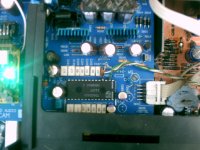
On DEM topic, I lifted the BCK resistor on the dac board to feed in 11.2 and 5.6 to pins 2 and 4 straight from the new clock.
Clock will also let me have 2.8 that I can send to 16 for DEM - useful.
You can see it in the pic attached - ( this was before the caps changes I made ) but you can see pins 2 and 4 with clock feeds and the CK resistor lifted.
Pic 2 - is this another DEM option using WS.
Can I feed 2.8 mhz to pin 16 this way then remove the 470pf styrene cap that connects 16 to 17 and then gnd 17 ?
It's so confusing - well for me anyway - maybe all the experts out there find this sort of stuff easy but tbh I'm scared to wreck all the reasonable work I've done so far.
CD Player sounds much better than original = reasonable work !!
Andrew
I'll be changing caps then....have many spares and will apply the logic of the junk box ! 😀
On DEM topic, I lifted the BCK resistor on the dac board to feed in 11.2 and 5.6 to pins 2 and 4 straight from the new clock.
Clock will also let me have 2.8 that I can send to 16 for DEM - useful.
You can see it in the pic attached - ( this was before the caps changes I made ) but you can see pins 2 and 4 with clock feeds and the CK resistor lifted.
Pic 2 - is this another DEM option using WS.
Can I feed 2.8 mhz to pin 16 this way then remove the 470pf styrene cap that connects 16 to 17 and then gnd 17 ?
It's so confusing - well for me anyway - maybe all the experts out there find this sort of stuff easy but tbh I'm scared to wreck all the reasonable work I've done so far.
CD Player sounds much better than original = reasonable work !!
Andrew
Attachments
- Status
- Not open for further replies.
- Home
- Source & Line
- Digital Source
- decoupling TDA1541A