Ok thanks guys, I have soldered the caps directly to the pins and it was a succes!
Next step is setting the Philips cd460 to NOS mode BUT i want to put a switch in between. Not sure on how to do this yet.
Thanks again for the help
Next step is setting the Philips cd460 to NOS mode BUT i want to put a switch in between. Not sure on how to do this yet.
Thanks again for the help
Well, You could try two dual relays attached to a switch, however, I guess you'll experience noise when switching from OS to NOS or the other way around.
Some might argue you'd hear noise switching into NOS mode (that's a joke! Don't flame me).
Just remembered - I'm running 1uF on my 2 most significant current sources and it works fine.
Not sure if it made a huge difference, but it did work.
Just remembered - I'm running 1uF on my 2 most significant current sources and it works fine.
Not sure if it made a huge difference, but it did work.
Hi,
In one Philips CD960 I have tried Sanyo oscons from 1uF to 47uFon all pins - still were working without any sensible distortion 😎.
However increasing values above 4,7uF of Oscons there was no sense - no any improvement in sound. So finally I left 4,7uF Sanyo Oscons soldered on all original 0,22uF MKP.
IMHO, one of best way is 0,22 - 1uF MKPs or Blackgates (N or NX) on all pins, except MSB - here value should be doubled or even trippled. If using oscon type capacitors, you need to triple all values, because of bigger tangent loss (DF). Increasing above 0,22uF (MKP) means more refined trebles, but less warm middles.😕
If you need really fine trebles (especially if using tube or coupling transformer), try use SMD X7R type capacitors in range 1 - 4uF per pin. Kemet 1206 size is really small and very low DF.
Quite: I've had no problem with 1uF or rather more (but 100nF really is enough)
The critical thing though - pick caps for minimal leakage current.
If you put a 'scope on these pins you soon see what's going on. The caps sink ripple voltage derived from the DEM ladder, and need ot work well at (multiples of) the DEM clock chosen* BUT each pin in the active ladder connects to that 'bit's internal current source SO *any* leakage current on the pin will directly f***-up dac linearity. Stick with film caps of your choice NOT electrolytics (and just don't bother with that BG nonsense)
*if you really want to know the internals there are plenty of references online. Assume each cap needs to work say >176Khz min and/or OS multiples thereof. So the cap must have aat least fair RF properties: very short leads, low-inductance design AND pcb layout for best effect.
Martin,
Funny you should say. Using fairly large value Os-Con's on the MSB Pin's measurably improved performance, despite clearly adding leakage current. So clearly your analysis is not entierly complete.
I found that HF impedance is really the most important factor, so low ESR and ESL trump almost anything else. Low microphonics are also generally desirable, so (piezo)ceramic types are not a good idea.
Ciao T
SO *any* leakage current on the pin will directly f***-up dac linearity.
Funny you should say. Using fairly large value Os-Con's on the MSB Pin's measurably improved performance, despite clearly adding leakage current. So clearly your analysis is not entierly complete.
I found that HF impedance is really the most important factor, so low ESR and ESL trump almost anything else. Low microphonics are also generally desirable, so (piezo)ceramic types are not a good idea.
Ciao T
Isn't it better to place the caps this way, rather than to align them?
The path seems shorter with this configuration
best to place the caps at the other side of the 1541, all pointing inwards. Obviously, a full groundplane should be present below the 1541.
best
Maybe; I think the other currents are derived from the MSB, so it alone is the one place you can get away with leakage.Funny you should say. Using fairly large value Os-Con's on the MSB Pin's measurably improved performance, despite clearly adding leakage current. So clearly your analysis is not entierly complete.
Agree with your other points.
Maybe; I think the other currents are derived from the MSB, so it alone is the one place you can get away with leakage.
Agree with your other points.
hi Martin
Thanks
The currents through the caps are not the only concern; The induced voltage in the groundplane adds to the capacitor voltages as well....
best
The device has clocks with 32ns rise times, there will be harmonics into the 100MHzs. Looking at the values on the data sheet these caps are for quite high frequency decoupling of internal noise. Small caps (physical size) as this minimises inductance (as pointed out before). A decoupling cap is not just capacitance, it is capacitance, inductance and resistance in series, it is the inductance that causes the most problems with switching noise. Another fuction of these caps is to minimise EMC, adding large capacitors with long leads is not recomended for EMC reasons alone.
Again MLCC capacitors seem to have bad press,😕 yet are used almost exclusively for decoupling, where the small sizes available and low inductance are more benefitial than other percieved problems, though best not to go below an X7R type. Used mostly in SMD format, the size of the device, mounting method and relative mass of the PCB means they are exposed to not enough vibration to have any effect in a decoupling role, COG NPO are used in RF coupling stages.
A lot of the mods go againts good digital design and layout practice, and while this design is pretty forgiving with quite slow rise times etc, I wouldn't recomend it as standard practice. The whole point of digital layout is to minimise the current loops of every signal, and at these frequencies it is minimising the inductive path.
A couple of intersting links:
Good recomendations, and some theory of signal return currents, and the use of ground planes with both digital and analogue circuitry on the same board.
http://www.x2y.com/filters/TechDay0...log_Designs_Demand_GoodPCBLayouts _JohnWu.pdf
http://www94.web.cern.ch/hsi/s-link/devices/g-ldc/decouple.pdf
MLCC😀
http://www.avx.com/docs/techinfo/mlcbypas.pdf
The 10 Best Ways to Maximize Emission from Your Product
Guido,
Can we use grounded (or maybe not) copper foil on the bottom of TDA1541 for screening purpose?
Maybe it would be reasonable to screen TDA1541 by foil loop - bottom and top?
marce,
Philips CD 304 MKII, Marantz CD40-60 and other similar design solutions are not worst for sure.
Here we can replace original SMD ceramic capacitors by bigger values of X7R kind.
But if MLCC SMD solution is so good, why engineers in Eindhoven decided not use SMD type in all higher level players of Philips/Marantz? Why they used here MKP/MKT 0.22uF with "long" leads?
Can be reason here lower leakage currents and lower microphonics as result of better and thicker dielectric? And that induction in capacitors which Guido has mentioned?
BR
best to place the caps at the other side of the 1541, all pointing inwards. Obviously, a full groundplane should be present below the 1541.
best
Can we use grounded (or maybe not) copper foil on the bottom of TDA1541 for screening purpose?
Maybe it would be reasonable to screen TDA1541 by foil loop - bottom and top?
marce,
The device has clocks with 32ns rise times, there will be harmonics into the 100MHzs. Looking at the values on the data sheet these caps are for quite high frequency decoupling of internal noise. Small caps (physical size) as this minimises inductance (as pointed out before). A decoupling cap is not just capacitance, it is capacitance, inductance and resistance in series, it is the inductance that causes the most problems with switching noise. Another fuction of these caps is to minimise EMC, adding large capacitors with long leads is not recomended for EMC reasons alone.
Again MLCC capacitors seem to have bad press,😕 yet are used almost exclusively for decoupling, where the small sizes available and low inductance are more benefitial than other percieved problems, though best not to go below an X7R type. Used mostly in SMD format, the size of the device, mounting method and relative mass of the PCB means they are exposed to not enough vibration to have any effect in a decoupling role, COG NPO are used in RF coupling stages.]
Philips CD 304 MKII, Marantz CD40-60 and other similar design solutions are not worst for sure.
Here we can replace original SMD ceramic capacitors by bigger values of X7R kind.
But if MLCC SMD solution is so good, why engineers in Eindhoven decided not use SMD type in all higher level players of Philips/Marantz? Why they used here MKP/MKT 0.22uF with "long" leads?
Can be reason here lower leakage currents and lower microphonics as result of better and thicker dielectric? And that induction in capacitors which Guido has mentioned?
BR
Youd have to ask the engineers. I would be interested on what devices and where these caps are before I can comment, but a 0.22uf is not decoupling the high frequency noise, you require smaller values to do that (1n, 10n & 100n are often used to give broadband noise decoupling. Lead inductance is one of the killers for de-coupling digital designs, if you look round at all the information on decoupling caps this is well documented, and long leads mean inductance.
At the end of the day digital noise is digital noise whether its a DAC for audio, or its a DAC on some control circuitry, or a PC. How digital noise is combatted is well documented, and as rise times of equipement increase, and clock frequencies get faster the problem of digital noise becomes more problematic to solve.
There is plenty of info out there regarding digital design, and EMC, and if you plane to do digital design it is worth re-searching.
Generaly de-coupling caps are placed on the power pins of a device, with varying values covering a range of frequencies. On high speed boards the first capacitance seen is the power/ground interplane capacitance, followed by the increasing values of caps, from very small next to the pins, to electrolytics (or Tants) acting as reservoir capacitors. Where rise times are slower and clock frequencies are low you have more leeway, but even a 32ns rise time has harmonics into the 100MHz range, start using a 1ns rise time and you have 1GHz harmonics.
In a decoupling role, with SMD devices the microphony of X7R and above dielectrics will not be a problem, as said they do get a bad press in audiophile circles, but are used in there millions throughout the world and tested in high vibration equipement with no adverse effects. I would not use anything other than COG/NPO for interstage coupling, though for most audio work the values available are not high enough, COG/NPO are used in RF designs, again with no problems.
As I have said following best practice for digital noise suppression is well documented and probably quite often goes against audiophile beliefs. Have a look at the info out there from Henry Ott, Howard Johnson, Eric Bogatin to name a few.
And when doing digital layout having a complete contiguous ground plane without any slots is best. Though not often in a DIYers mind EMC is a big problem and getting worse.
Last edited:
Hello marce,
About piezoelectric effects:
From Linear Technology, LTC6655 datasheet (0.25ppm Noise, Low Drift Precision Buffered Reference Family)
quote:
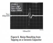
"For very low noise applications where every nanovolt counts, film capacitors should be considered for their low noise and lack of piezoelectric effects. Film capacitors such as polyester, polystyrene, polycarbonate, and polypropylene have good temperature stability..."
The picture come from Linear Technology, LT1763 datasheet.
Using capacitors with long leads is never a good practice. For low noise application, many manufacturers recommend to NOT USE X7R capacitors.In a decoupling role, with SMD devices the microphony of X7R and above dielectrics will not be a problem, as said they do get a bad press in audiophile circles, but are used in there millions throughout the world and tested in high vibration equipement with no adverse effects.
About piezoelectric effects:
From Linear Technology, LTC6655 datasheet (0.25ppm Noise, Low Drift Precision Buffered Reference Family)
quote:
"For very low noise applications where every nanovolt counts, film capacitors should be considered for their low noise and lack of piezoelectric effects. Film capacitors such as polyester, polystyrene, polycarbonate, and polypropylene have good temperature stability..."
The picture come from Linear Technology, LT1763 datasheet.
Attachments
From Linear Technology, LTC6655 datasheet
quote:
"In order to achieve the best performance, caution should be used when choosing a capacitor. X7R ceramic capacitors are small, come in appropriate values and are relatively stable over a wide temperature range. However, for a low noise application X7R capacitors may not be suitable since they may exhibit a piezoelectric effect. The mechanical vibrations cause a charge displacement in the ceramic dielectric and the resulting perturbation can look like noise."
I know about at least one Philips CD player where SMD decoupling capacitors are used at the underside of the TDA1541A chip.
I know about at least one Philips CD player where SMD decoupling capacitors are used at the underside of the TDA1541A chip.
Almost all of Philips and Marantz CD players based on TDA1541 are with SMD decoupling capacitors below the chip.
Only few players from long Philips/Marantz list are with non SMD capacitors, and all of them are well known for their sound quality:
Philips CD-880 and CD-960 (DAC-960 also), Marantz CD80, CD94, CD94MK2, CD-7 too.
All Naim TDA1541 players also have non SMD decoupling.
In all those cases long pcb tracks were inevitable, as here were used thick (higher voltage rating, less microphony and leakage current) MKP or MKT capacitors.
By the way, only in Philips CD-960, -880 and both marantz CD-94 were used 220nF capacitors, in all others were used 100nF.
So 100nF should be enough and this is completely true - Naim CD-3 sounds far better than any of above mentioned players, just because power supply is ok, as should be.
Hi,
Naim used rather compact stacked film Cap's from Epcos, notable for their excellent HF behaviour.
Naim's layout is quite good actually.
Ciao T
All Naim TDA1541 players also have non SMD decoupling.
Naim used rather compact stacked film Cap's from Epcos, notable for their excellent HF behaviour.
In all those cases long pcb tracks were inevitable,
Naim's layout is quite good actually.
Ciao T
Hi ThorstenL,
Have you got any reference or picture of those capacitors?Naim used rather compact stacked film Cap's from Epcos, notable for their excellent HF behaviour.
Eric - here is a typical Naim implementation:
- It's not clear in my pic, but the caps return to a ground plane tied to the dac's own 0v plane.
An externally hosted image should be here but it was not working when we last tested it.
- It's not clear in my pic, but the caps return to a ground plane tied to the dac's own 0v plane.
Last edited:
- Status
- Not open for further replies.
- Home
- Source & Line
- Digital Source
- decoupling TDA1541A