
"0.33 is the max I found for SMD
for leaded maybe they can be bigger"
well for starter leaded 0.1uF C0G is expensive, and hard to obtain , at least locally.
"and you can stack smd"
not a good idea, unless done correctly, for example how to clean the flux ?😉
Hartono
for leaded maybe they can be bigger"
well for starter leaded 0.1uF C0G is expensive, and hard to obtain , at least locally.
"and you can stack smd"
not a good idea, unless done correctly, for example how to clean the flux ?😉
Hartono
Having spent a lot of time reading:
http://www.lampizator.eu/LAMPIZATOR/TDA1541 corner/TDA1541.html
I decided to use 0.47uf BG NX caps. Hopefully they'll be arriving soon.
http://www.lampizator.eu/LAMPIZATOR/TDA1541 corner/TDA1541.html
I decided to use 0.47uf BG NX caps. Hopefully they'll be arriving soon.
My schematic shows that TDA1541A's supply pins are decoupled with 33u caps bypassed with 22n ceramic caps.
Would it be a good idea to try 82uf Pana FC or 100uf Silmic caps bypassed with 0.082uf metallised polypropylene caps and do the same for SAA7220 decoupling? Have got some lying around 🙂 Or... would it be better to leave the 22n bypass values, of which I have some metallised polyester caps.
I don't have os-cons available.
I bring this topic up. I can confirm that pin 13 is MSB for R channel, and pin 18 is MSB for the L channel (if the TDA1541A is driven with I2S signal). I tried 22uF tantalum capacitors on pins 12, 13, 18 and 19. The result was catastrophal as I described it in this thread on the same subject:
http://www.diyaudio.com/forums/showthread.php?postid=1459540#post1459540
I was also thinking over the operation and found that the MSB is responsible for the positive half period of the analog output signal only. It has no effect on the negative half period.
http://www.diyaudio.com/forums/showthread.php?postid=1459540#post1459540
I was also thinking over the operation and found that the MSB is responsible for the positive half period of the analog output signal only. It has no effect on the negative half period.
I can not tell that because I modified also other things. I will try some suitable size MKP capacitors.
It makes sense, but 1uF might be too much - manufactures didn't go over 470nF.
Also, don't know if it was for economical reasons, but they didn't use different values.
Also, don't know if it was for economical reasons, but they didn't use different values.
Do you think it could damage the dac to go over 1uf ?
Good Question, ????????
Good Question, ????????
I have been using several TDA1541A S-1 chips with 1.68uf (1uf in parallel with 0.68uf) Philips stacked film bypasses since 1988 without any problems whatsoever. Probably would not have been my first choice if I had more space, but they have withstood the test of time. Sound pretty good too, IMHO.
The Wima MKS-2 1.0uf also works well and is small enough to fit most existing boards without crowding.
I've been using a Studer A 727 for a decade, stumbled over it in a local storage unit and was told by the Junkman that he wouldn't accept less than $50 cash...😱
..it was a tough decision but someone had to make it 😀
So... I believe it uses the earlier 1541 non-A non-S1/2 chip, but is absolute heaven to listen to.
I've auditioned Levinson, Mission, Cambridge, Cal Labs, etc., and all have detail but the Studer has music, 'liquid sonics' as a friend (who is weighed down with the ball & chain of Denon equipment) put it.
Am I missing out by not having a newer rendition of this 'God's gift' chip series?
Hello to all,
I'm a newbie and i have a question. Is it possible to solder the decoupling cap straight to the pins of the TDA?
Thnx in advance.
I'm a newbie and i have a question. Is it possible to solder the decoupling cap straight to the pins of the TDA?
Thnx in advance.
I've no idea where I found this - I probably downloaded it from a forum (probably this one) years ago. So, not my work, but probably the closest method to soldering big caps to the pins. Not sure I'd risk soldering straight to the pins myself - but that's because I don't have many TDA1541As going spare these days. You probably could do if you're quick (CD manufacturers did), but it's just safer using a socket.
Attachments
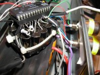
Hi,
I did this on my original adagio.
Wrapped the IC into copper foil which was used as groundplane and all components hard-soldered to the pin's (not just decoupling cap's, also 431 Shuntregs and other stuff...
A bit hardcore perhaps, for most.
Ciao T
I'm a newbie and i have a question. Is it possible to solder the decoupling cap straight to the pins of the TDA?
I did this on my original adagio.
Wrapped the IC into copper foil which was used as groundplane and all components hard-soldered to the pin's (not just decoupling cap's, also 431 Shuntregs and other stuff...
A bit hardcore perhaps, for most.
Ciao T
- Status
- Not open for further replies.
- Home
- Source & Line
- Digital Source
- decoupling TDA1541A