Although the circuit for this project is relatively simple it becomes more complicated when it comes to planning actual hardware.
I mentioned heat sink in a previous post and suggested a minimum of 0.3 degree C rating per watts of dissipation per module. These will be probably be large enough to form two sides of the case housing for the whole.
If regulated supplies or voltage multipliers are in the plan you will need extra heat sinks appropriate to the rating and these will need extra space.
If you take the unregulated supply route then you are going to need 30,000 or more uF per rail and this poses a further accomodation problem within one chassis -especially if you select caps with the best ripple specs.
I can tell you a 300 v.a. transformer rated at 22-0-22 produces 31 volts after rectification and I use it to power a pair of Class A modules. The supply is regulated to deliver 22 volt rails at the output. The current draw is 2 amps per amplifier module. The transformer and heatsink for the power supply generate a substantial amount of heat and with large capacitors the supply takes up a lot of space - such I made a separate housings for the amplifier and the supply which are connected by a detachable cable.
This isolates the heat from adding to that generated by the amplifier - it also isolates stray fields from the toroidal transformer and any vibration or microphonic effects.
This is an elaborate way to go and a simpler route would be to use an unregulated supply using the suggested heatsinks and caps.
Larger transformers will generate less heat and the secondary voltages should be what you expect to use under load.
Unfortunately there are not too many choices off the shelf in New Zealand and if precise voltages are specified then you have to put in an order to a manufacturer and pay a premium for that.
For instance there is a small but significant difference between the rectified output voltage of a 15-0-15 a.c. transformer and one of 18-0-18 a.c. in terms of current draw for power rating heatsinking etc.
If you want to avoid having to replace transistors from time to time I recommend the conservative 15-0-15 voltage rating.
You could get away by using a 160 v.a. transformer and see how you go with that.
I expect a 300 v.a. one would be better. You could allow space for tthe larger component if you take that option however you could also leave space for a second 160 v.a. transformer for a future upgrade. You could use the existing capacitors with the separated supply bridges.
Michael J
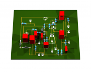
This is my pcb:
Notes
Any comments on the pcb or the options I've made would be really appreciated!
Thank you a lot!
(I'm attaching a picture + the eagle files, I hope they are useful to someone coming next!)
Notes
- I'm using the same schematics from the project's website.
- I'm using a 4700uF as output decoupling cap.
- The blue boxes are the pcb fixing points.
- The BD139's will have an aprox. 3x3cm heatsink
- The output stage will use 2n3055's because them are the only available ones I can find with my local supplier from the options you discused earlier.
- I'm planning to get a new 22v@150VA power transformer with 2x10mF caps and a 10mHy choke. Should I still use the 12v+12v zeners or should I lower the voltage to something like 18-20v?
- I'm using 0,4mm copper wires. It's that OK?
Any comments on the pcb or the options I've made would be really appreciated!
Thank you a lot!
(I'm attaching a picture + the eagle files, I hope they are useful to someone coming next!)
An externally hosted image should be here but it was not working when we last tested it.
Attachments
I don't think this layout will work well. Many of the capacitor shapes you've chosen are too small for the values shown. Have you measured the dimensions of the actual components you will use, to see if they will fit?
PCB tracks could be much wider, and should be in all the places where large currents may flow. Also consider curvier tracks, but that's not as important here.
Do you plan to use SMD trimmers? You don't need to, and it will probably be easier to assemble if you don't.
Are the BD139s going to be bolted thru their heatsinks to the board? If so, you must make room for the heatsinks and move the tracks out of the path of the mounting holes. Even if they are to be mounted vertically, you still need to decide what style of heatsink you will use, and make sure the component layout can accommodate them.
Have you drawn all the tracks on the top side only? Eagle defaults with red for topside tracks and blue for bottom side tracks. If you're going to etch the board yourself, I recommend doing all the tracks on the bottom side.
Last edited:
I'm going to etch it myself so top and bottom layers will become the same layer. I used blue for planes for a friendlier layout on Eagle.
The size of the caps was taken into consideration, now it's displayed correctly.
Now the output stage uses a 1mm line and the ones carrying a large current now are double-sized.
The trimmers shape is quite dependant on the supplier and will be adjusted when I have all the components.
The BD's will have a heatsink like the one on the picture. It's quite light so I was planning to solder them vertically with the heatsink bolted to the transistors.
A ground plane like the one shown should dismiss the effects of ground loops right? Or should the 3 rightmost ( Death of Zen - A new Class-A power amp ) ground be connected on a different plane?
Thank you a lot for your insight!
An externally hosted image should be here but it was not working when we last tested it.
An externally hosted image should be here but it was not working when we last tested it.
An externally hosted image should be here but it was not working when we last tested it.
An externally hosted image should be here but it was not working when we last tested it.
Hi agus.

Nice layout.
Some thoughts:
1. Use 20k for VR1.
2. C8 goes from base of input bjt to ground.
3. Place the VCC header so that it meets the 3055's collecter and then the BD. Or, separate tracks for each stage.
4. If your PS output is 40V or more, use 15V zeners.
All the best.

This thread is very interesting.
interesting observations. About the URL
The Class-A Amplifier Site - JLH Class-A Update
you will find a reporting about differences between 2N3055 and MJ21194 (JLH-amp) - also very interesting.
In this case this thread could be also of interest:
http://www.diyaudio.com/forums/soli...istor-families-audio-power-output-stages.html
For me it would be interesting to know the audible difference to the JLH. I have heard both, unfortunately not at the same time in the same chain. The most important difference in the circuit difference between both are the kind of driving the upper BjT device Q2: At JLH Q7+8/R12 VR2 abd at DOZ (post #4) Q4, R15, so as R1, R2, R3 and C4. The two different approaches for reduce the offset voltage haven't great influence to the sonic character - so I think.
Into 8ohm load, I found no difference between them when TIP3055 is used with DOZ and 2SC5200 used with JLH'69. When I revert the transistors an interesting thing happens. DOZ sounds too bright with 5200(HF oscillation?) and JLH sounds okay with 3055, although with less treble. JLH seems more forgiving to transistor varieties.
Still, I chose DOZ as my favorite as, when used with cheap 3MHz transistors, 1) it has perfect balance in bass, vocal, treble; I can listen all day without getting bored and 2) My 4ohm speakers sounds equally fantastic to 8ohm ones with DOZ, JLH didn't pass this test.
Thanks for the kind words.

interesting observations. About the URL
The Class-A Amplifier Site - JLH Class-A Update
you will find a reporting about differences between 2N3055 and MJ21194 (JLH-amp) - also very interesting.
In this case this thread could be also of interest:
http://www.diyaudio.com/forums/soli...istor-families-audio-power-output-stages.html
For me it would be interesting to know the audible difference to the JLH. I have heard both, unfortunately not at the same time in the same chain. The most important difference in the circuit difference between both are the kind of driving the upper BjT device Q2: At JLH Q7+8/R12 VR2 abd at DOZ (post #4) Q4, R15, so as R1, R2, R3 and C4. The two different approaches for reduce the offset voltage haven't great influence to the sonic character - so I think.
Last edited:
The most important parts in the DOZ circuit IMO are the 100R base-emitter resistors. A quick sim shows cleanly how the slew decreases as any of these resistors' value is increased. And not only that, their values have a direct effect on the distortion spectra too. Both the '69 and '96 versions of JLH10 use a 2K7 for the lower power transistor and none for the upper. Of course, the presence of the low-ish value resistors there means that the current source has to supply double the current(hence double the dissipation) to adequately bias the power stage. But the addition of these two resistors seem to better suppress all the harmonics beyond the second, which I think is an interesting and useful behavior and also the very 'warm' sound that DOZ produces comply with the simmed spectra. This, however, happens only when the power stage is biased at 1600mA or more, probably the reason why Rod suggested an Iq of 1.7A as an optimum bias for DOZ.
And, as a compensation capacitor is not welcome, so not is an ultrafast BJT. Superb music can be produced with a pair of a dollar worth of slow BJTs, e.g. TIP3055.
shaan
And, as a compensation capacitor is not welcome, so not is an ultrafast BJT. Superb music can be produced with a pair of a dollar worth of slow BJTs, e.g. TIP3055.
shaan
Hi AgusR,
When using Eagle always run Tools > ERC and DRC and fix the errors.
I would suggest you change the lead spacing of your resistors. 7 mm is very tight for standard resistors. I would recommend 10 mm as a minimum, you have plenty of space.
Why are you using surface mount for the pots?
Double check the size and efficiency of your heat sinks, my DoZ ran very hot.
BTW: Most of us at DIYAudio would encourage you to just buy the PCBs from ESP.
Attachments
Last edited:
You are right - that is well understood. Maybe this is also the main reason for the observed sonic differences at the JLH by the use of modern BjTs in the output. If there (in JLH) also would use these base emitter 100R resistors, the audible sonic differences would potentially been much less between different output power BjTs.The most important parts in the DOZ circuit IMO are the 100R base-emitter resistors. A quick sim shows cleanly how the slew decreases as any of these resistors' value is increased. And not only that, their values have a direct effect on the distortion spectra too. Both the '69 and '96 versions of JLH10 use a 2K7 for the lower power transistor and none for the upper. Of course, the presence of the low-ish value resistors there means that the current source has to supply double the current(hence double the dissipation) to adequately bias the power stage. But the addition of these two resistors seem to better suppress all the harmonics beyond the second, which I think is an interesting and useful behavior and also the very 'warm' sound that DOZ produces comply with the simmed spectra. This, however, happens only when the power stage is biased at 1600mA or more, probably the reason why Rod suggested an Iq of 1.7A as an optimum bias for DOZ.
And, as a compensation capacitor is not welcome, so not is an ultrafast BJT. Superb music can be produced with a pair of a dollar worth of slow BJTs, e.g. TIP3055.
shaan
You are right - that is well understood. Maybe this is also the main reason for the observed sonic differences at the JLH by the use of modern BjTs in the output. If there (in JLH) also would use these base emitter 100R resistors, the audible sonic differences would potentially been much less between different output power BjTs.
DOZ's emitter-out CCS isn't really as fast as the collector-out CCS of the '96 JLH, and also it's not using a reference - purely base current driven.
Fast removal of base charge is The main reason the resistors are low in value. Although Rod seems not too happy with the results...
I believe this will be the final version of the pcb.
I reconnected the C8 cap to ground (instead of to Q1's collector as on the schematic).
I read on another topic that in order to reduce noise, signal's ground should be connected using a different wire to a star ground on the power source. So I decided to split the ground from Vin, C6, C2, R12 to a different from the main one.
The VCC pin was moved so it would be closer to Q3's collector.
(Note: I am designing the pcb myself instead of buying it directly from Westhost due to the extremely long process of importing something to my country. Books buyed from amazon take at least 2 to 3 months to arrive.. (technically they arrive in 1 month and are retained for quite a few more on customs office..))
An externally hosted image should be here but it was not working when we last tested it.
Today's afternoon I'm planning to finish soldering the amp for a test.
I did found something odd on the LtSpice simulations. One of the output transistor dissipates 2-3 times more power than the other one. In particular, the one that dissipates more power is the 2n3055 with the emiter resistor. Did I screw something with LtSpice schematic or it really works this way?
I did found something odd on the LtSpice simulations. One of the output transistor dissipates 2-3 times more power than the other one. In particular, the one that dissipates more power is the 2n3055 with the emiter resistor. Did I screw something with LtSpice schematic or it really works this way?
Did you set the voltage at the collector of the lower power transistor with the 100k trimmer at the input? If trimmer isn't available in sim then connect two 50k resistors in series, from +ve to ground. And connect the 100k at the base of the input transistor to the middle junction of the resistors. Then you can control the voltage at output by varying any of the series connected resistors.
Hi all,
This is my first message so be indulgent !
I fall in the audiophile world some years ago, beginning with buying some nice little market amp (NAD310 / NAD325 / Advance MAP-101).
So, as i'm a diy guy since my childhood, i'd like to mount one class A. I found some design like "Le monstre", JLH1969, ZEN, SoZ, Aleph, DOZ and others.
I finally decided to mount one DoZ.
My goals (who said challenge ?) are :
- tiny box (220x170x55)
- fan ventilated (40mm 12V low-noise fan...), with managed air flow.
- single-ended 35V (one 200VA/2x24v transformer output per channel)
- 15w on 8 ohm speakers (Heybrook HB3 Series 2)
I realize it's not in mentality of most of your feat, but i like do thinks not like everyone ;o)
I draw a schematic of the box with transformer, capacitors (4x22mF), heatsinks, ... very narrow but OK. I have the place for 2 main mono boards (50x100mm).
Do you think it's realistic ?
Could you please advise me for transistors to use (plastic versions for little space reasons) ?
Regards,
Mick
Assemble a temporary prototype for just ONE channel.
Get it working.
Get it performing properly and well.
Then see how small you can package this ONE channel.
Will it fit the box you desire?
Buy box that fits.
Get it working.
Get it performing properly and well.
Then see how small you can package this ONE channel.
Will it fit the box you desire?
Buy box that fits.
Thanks for the reply Andrew.
But the system can't operate if not in the final box because it actively participate to the flow management.
All fit theorically in the box. The air flow is totally ducted through the heatsink (18.6m3/h).
I think i can use the original Westhost PCB, so not really anxious that it will work. My doubts are only for :
- the transformer power (is 200VA OK?)
- capacitors : is 2x22mF per channel too fat ? May be 2x10mF is sufficient ? And if my main power is at 34V, could i use 35V capacitors (for gain of place) ?
- what output capacitors to use ?
- transistors : MJL4281 / MJL21194. Which one do you recommend ?
- HP protection : is it necessary as i have seen many people use this kind of protection ? Are the speakers protected from burning transistors without ?
- can i use the main power of the amp to supply the fan (0.6w) with filtering. Maybe around the D2 12v zener ?
Thanks to spend some time for me !
Mick
Why? Just get the amp working....................
But the system can't operate if not in the final box...................
Thanks Andrew.
As explained, the box participate actively to the air flow management.
If i use the original PCB from Westhost, there is no reason the amp is not OK.
But i would like to know if the 200VA transformer is enough before buying it, cause it's an expensive device ...
Have you some ideas for the other questions of my previous post ?
- Home
- Amplifiers
- Solid State
- Death of Zen 15 watt Power Amplifier