


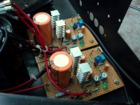
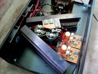
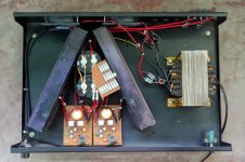
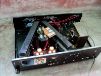
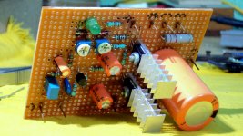
Fresh stereo DoZ for a local friend. 😎
Attachments
-
 DSC03819.JPG359 KB · Views: 433
 -
 DSC03821.JPG284.8 KB · Views: 389
 -
 DSC03815.JPG433.1 KB · Views: 353
 -
 DSC03789.JPG397.1 KB · Views: 381
 -
 DSC03779.JPG315.9 KB · Views: 383
 -
 DSC03785.JPG411.2 KB · Views: 994
 -
 DSC03813.JPG331.2 KB · Views: 989
 -
 DSC03812.JPG363.3 KB · Views: 999
 -
 DSC03811.JPG292.5 KB · Views: 1,035
 -
 DSC03810.JPG382.5 KB · Views: 1,101

Mounting criticism:
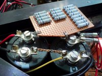
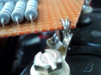
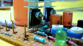
Do not mount the transistors in close proximity to each other using these heat sinks. Place a transistor in the second space and the other in the fifth space (counting from one edge of the heat sink).
The use of a single transformer for a stereo amplifier is contradictory, if the goal is a good channel separation.
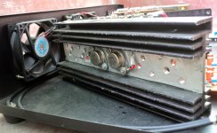
The ventilation system is bad for this type of amplifier.
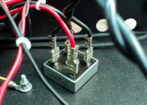
The cable for low signal travels a long distance through electrically noisy environments. The volume potentiometer should be located as close as possible to the inputs of each of the two amplifiers. The piece of shielded cable (placed between the potentiometer and the inputs of the two amplifiers) causes a sharp roll off at high frequency. A small contact resistance at the potentiometer worsens the effect (in position of maximum volume). The best location for the potentiometer is somewhere between the two PCBs. The connectors for low signal, not far from the potentiometer (in the front), and quite far from the outputs to the speakers.
The main filter capacitors should be well away from the heat sinks.
The output cables to the speakers should be very short.
Regards
Do not mount the transistors in close proximity to each other using these heat sinks. Place a transistor in the second space and the other in the fifth space (counting from one edge of the heat sink).
The use of a single transformer for a stereo amplifier is contradictory, if the goal is a good channel separation.
The ventilation system is bad for this type of amplifier.
The cable for low signal travels a long distance through electrically noisy environments. The volume potentiometer should be located as close as possible to the inputs of each of the two amplifiers. The piece of shielded cable (placed between the potentiometer and the inputs of the two amplifiers) causes a sharp roll off at high frequency. A small contact resistance at the potentiometer worsens the effect (in position of maximum volume). The best location for the potentiometer is somewhere between the two PCBs. The connectors for low signal, not far from the potentiometer (in the front), and quite far from the outputs to the speakers.
The main filter capacitors should be well away from the heat sinks.
The output cables to the speakers should be very short.
Regards
Mounting criticism:
Do not mount the transistors in close proximity to each other using these heat sinks. Place a transistor in the second space and the other in the fifth space (counting from one edge of the heat sink).
As it turned out after a few months of continuous use, the heatsinks were overkill for the job. The fans are run with huge series resistors to slow them down and even this minimal airflow worked more than sufficient. 🙂
The use of a single transformer for a stereo amplifier is contradictory, if the goal is a good channel separation.
The answer lies in good grounding practices. I think I did fine coz neither I nor the customer could complain about crosstalk. 🙂
The ventilation system is bad for this type of amplifier.
Not at all. Although not shown, the top and sides of the case has ample slits to allow for very good cooling of the hearsinks. Also the placement of the heatsinks were selected to ensure that most of the incoming airflow blows all over its surface. Turned out, it works. 🙂
The cable for low signal travels a long distance through electrically noisy environments. The volume potentiometer should be located as close as possible to the inputs of each of the two amplifiers. The piece of shielded cable (placed between the potentiometer and the inputs of the two amplifiers) causes a sharp roll off at high frequency. A small contact resistance at the potentiometer worsens the effect (in position of maximum volume). The best location for the potentiometer is somewhere between the two PCBs. The connectors for low signal, not far from the potentiometer (in the front), and quite far from the outputs to the speakers.
Those were temporary connections for testing only; no way they can be left as is. The potentiometer is close to the amp boards enough. A maximum volume for this kind of amplifiers are prohibited for quite a few practical reasons like excessive distortion and loss of soundstage. So the volume pot is usually at 25% to maximum 50% coz we got a preamp for it. 🙂
The main filter capacitors should be well away from the heat sinks.
The heatsinks are 50C - 55C at all times, no higher. The caps are rated 105C. 🙂
The output cables to the speakers should be very short.
Death of Zen isn't the everyday amplifier we are used to. It's stability is what builds its name. I can vouch for that coz even though the input and output terminals were close to each other, nothing happened, nothing. However, as I mentioned earlier, the input connectors has been moved closer to the amp boards' input side. 🙂
Thanks for posting.
With a symmetrical distribution of transistors on heatsinks could have avoided the use of coolers (obviously with heatsinks outside the cabinet).
A good grounding technique is not an option, it is a mandatory practice to follow to get acceptable results. The use of two transformers to feed a stereo system greatly reduces all interaction between channels (rather than using only a good grounding technique).
Any potentiometer arranged before the input of an amplifier and set well below the maximum, cause a marked deterioration in the high frequencies by the action of the parasitic capacitance to ground of the cable between the central contact of the potentiometer and the amplifier input. That's why I suggested that this cable should be as short as possible.
Any effort to keep the main capacitors at the lowest possible temperature is very positive for longer life.
Regards
Last edited:
The heatsinks are by necessity inside, and as I mentioned earlier they are cold enough for 60W dissipation each.
Good grounding technique is the utmost important practice to eliminate crosstalk, more so than using pure silver cables or two transformers. There is no crosstalk in this system as this is not a class-ab/d amplifier and the quiescent current is steady 1.5A for each channel. They do not share a common ground wire anywhere in the circuits. The voltage gradients occurring at the common ground point at the time of music playback is near zero because of its near zero resistance. You probably missed that all ground wires are terminated to the capacitor terminal.
The cable capacitance is a reality though. A minimum of it is quite unavoidable.
As I said the caps are happy with the temp inside and will probably run for 20 years without any problem. But, they are subject to replacement after ~10 years of operation, regardless of whether they are okay or not.
The heatsinks are by necessity inside, and as I mentioned earlier they are cold enough for 60W dissipation each.
120 watts of heat dissipation inside the cabinet!!! 😱😱😱
Not very good idea 😉
You probably missed that all ground wires are terminated to the capacitor terminal.
I have not supported that.
From what you can see on your amplifier: transient flow through common cable between both channels. 😉
The cable capacitance is a reality though. A minimum of it is quite unavoidable.
The parasitic capacitance is inevitable, that is true. It is also true that you can minimize its effect: driving the amplifier input from a very low output impedance (providing volume control at a strategic point in the preamplifier, instead of the amplifier). 😉
Ragards
PD: I am relying on the photos you 've uploaded. If you subsequently changed the layout, I can not see it. I am giving an opinion on what I see.
Last edited:
120 watts of heat dissipation inside the cabinet!!! 😱😱😱
Not very good idea 😉
Unless you know how to get rid of that heat. 😉
From what you can see on your amplifier: transient flow through common cable between both channels. 😉
There are no common cables for both channels, neither power nor signal. Transient flow in the power cables occur at near Iq speaker current and the cables are separate for each amp, so even if that does happen, no audible interaction, like in a class-AB amp where supply hum is superimposed over the signal at high volume making the hum inaudible. 😉
The parasitic capacitance is inevitable, that is true. It is also true that you can minimize its effect: driving the amplifier input from a very low output impedance (providing volume control at a strategic point in the preamplifier, instead of the amplifier). 😉
I think I mentioned a preamplifier in one of the last posts. 😉
PD: I am relying on the photos you 've uploaded. If you subsequently changed the layout, I can not see it. I am giving an opinion on what I see.
The only thing changed are the input cables and the potentiometer, which, as I agreed with you earlier, are in wrong places as shown in the photos. Everything else is intact. 🙂
Thanks for the input.
It is very obvious that you are mixing concepts, or perhaps you do not have very clear.
The "Death of Zen" drains constant current only if there is no signal in the input. When signal is applied: there are transients (due to the music) through common supply wires between both channels.
There are transients (due to the charge of main capacitor) flowing through common supply wires between both channels, if there is no signal in the input of both channels. These transients may be altered by one or both channels (when signal is applied).
I built several amplifiers in pure class A and I can assure you it is not easy to dissipate 120 W in a semi closed cabinet. The use of coolers for low power amplifier ruins the subtle difference that can be seen operating the amplifier in class A.
Using a potentiometer volume control on the input of an amplifier is a technique that has been overtaken by other much more effective. If you moved the volume pot, does not appear in the photos. Sorry, it is what I saw.
Anyway, if you are not willing to accept constructive criticism, I can not say more.
Regards
Hi diegomj.
I built absolutely "zero" Class-A amplifiers till now. I am such an "amateur" compared to your "experience" regarding amplifier building that I am "ashamed" to even be here.
Since your initial intent was solely "constructive" criticism and then later on figuring out "obvious" concepts about me, I would like to remind you this - you're posting wrong things in the wrong place. This is not the CFA vs VFA thread.
If you have nothing to share regarding your own DoZ build and have only "constructive" criticism in your bag, then refrain from posting here. Much appreciated.
If you want to start a fight use the private message system (it's free). We can throw as many "obviously" "maybe you are" etc. at each other as we want without spitting mud in public and degrading the beauty of this forum. 😀
Thanks again. 🙂
shaan
In each post I've done here, I have suggested a lot of areas for improvement (indicating how to do). It never has been intended to fight. They were positive contributions from me.
Having admitted yourself that you are a beginner, every post in which you have answered me you have highlighted your refusal to accept suggestions.
We must be humble enough to accept suggestions. Much more if we admit being beginners.
There is a saying that appointment: "No more blind as those who do not want to see".
Greetings and good luck with your project. As I said, I have nothing more to say.
Hahahaha now this is pretty amusing. I am literally rolling on the floor as I type this. 
Thanks for the last comment it will help restore the cheerful mood of this thread.
Wish you BEST OF LUCK with any project you build (if at all) hahahaha
Thanks for the last comment it will help restore the cheerful mood of this thread.
Wish you BEST OF LUCK with any project you build (if at all) hahahaha
If you have changed the location of the potentiometer (and all things that you have improved in the same amplifier) , you can show the picture today of how it looks.😉
Last edited:
That ship has sailed.
Bye and good day.
The answer was obvious. 🙄
Bye and good day, too.
Last edited:
😉
Okay let's move on. Love/Peace
To the new viewers - Feel free to share your DoZ experience here. If you're confused about the topic then please read Post #1. Thank you. ^^
shaan
Okay let's move on.
Love/Peace To the new viewers - Feel free to share your DoZ experience here. If you're confused about the topic then please read Post #1. Thank you. ^^
shaan
shaan, please
First thanks for share your work.
Is this modushopbiz case enough for heat dissipation:
Ok sounds a primary question but I had to confirm
Dissipante 04/300N 4U 10mm NERO.
Heatsinks are 165x300x32mm
I´m planning also to use Rod Elliot´s pcb´s
Death of Zen - A new Class-A power amp
In advance, thanks for comments.

- Home
- Amplifiers
- Solid State
- Death of Zen 15 watt Power Amplifier