Hi WM,
I was just sticking your DoGC schematic into Eagle and noticed that the feedback cap (3,300uF) *may* be the wrong way round???
I haven't seen anyone else mention it, so I might be confused (again). 😀
regards
I was just sticking your DoGC schematic into Eagle and noticed that the feedback cap (3,300uF) *may* be the wrong way round???
I haven't seen anyone else mention it, so I might be confused (again). 😀
regards
Greg Erskine said:Hi WM,
I was just sticking your DoGC schematic into Eagle and noticed that the feedback cap (3,300uF) *may* be the wrong way round???
I haven't seen anyone else mention it, so I might be confused (again). 😀
regards
You are right Greg.
And if you read this thread, widowmaker has removed it, in a later version.
When he did, my comment was, that cap did not do anything of value and could be removed.
When feedback resistors are as low as 1000/27 Ohm in compare of input 47.000 Ohm
cap will not correct any offset worth mentioning.
Not even if using bipolar input pair.
Speaking bipolar input pair, with some uA bias currents.
The difference 47.000/1000 or 47.000/25 does not matter
what would matter is
if was 47.000/47.000
this was my comment
and you confirm
Thanks lineup,
I had read it, but had a memory failure. 😀 I was working from the original schematic rather than the more complicated second version.
regards
I had read it, but had a memory failure. 😀 I was working from the original schematic rather than the more complicated second version.
regards
:-D
I (still) have probs with DC offset in new version.
In first 1/2 hour amp has 80-90mV, after that DC offset going between +10÷15mV and -10÷15mV...
2x2SK184BL for diff stage...
I (still) have probs with DC offset in new version.
In first 1/2 hour amp has 80-90mV, after that DC offset going between +10÷15mV and -10÷15mV...
2x2SK184BL for diff stage...
If I should change one thing
I would change where that 15 kOhm, that feeds IRF620 Gate,
gets its current.
Now when connected to BC639 Emitter ( lets call this transistor T3),
it can effect the current balance of input stage.
I would connect 15 kOhm to same T3 Base instead. (= the first BC639 Emitter )
Or maybe even better, give this resistor its own BC639, parallel with T3.
If this will fix the DC-offset variations, you have to test.
If we are lucky, it will.
Another thing I dont like at all, is very low current in resistor 15k to drive IRF620.
What I can see is like 0.5 mA ......
I think you have 5 mA in each T1/T2, to drive MOSFET IRF9610.
I would want to use same 5 mA to drive IRF620.
If we are talking about different versions,
then you have to tell the schematic you are using.
Otherwise I am just as lost as anyone else popping in here
and start figuring things out.
🙂
then you have to tell the schematic you are using.
Otherwise I am just as lost as anyone else popping in here
and start figuring things out.
🙂
No, we're talking about basic version 🙂
The problem is difference between input and feedback resistors,
in this cause 47k vs 500 ohms...
lineup, my icq # is 57231509 😀
The problem is difference between input and feedback resistors,
in this cause 47k vs 500 ohms...
lineup, my icq # is 57231509 😀
Widowmaker
you might have a look at using
input bias current compensation
I started a little thread, but not much interest.
I find it very useful!
I will make post so you can find my topic.
😎 Offset Correction using Bias Compensation 😎
you might have a look at using
input bias current compensation
I started a little thread, but not much interest.
I find it very useful!
I will make post so you can find my topic.
😎 Offset Correction using Bias Compensation 😎
Has widowmaker disapeared. I have tried to get in touch with him for the last 2½ week but he seem out of circulation. I have paid for some stuffed PCB's througt Wetsteren union, (perhaps not the cleverest thing to do, but I trust people). I am still waiting for the items to arrive. He promised to mail me shipping details. But nothing, just silence.
Michael Børresen
Michael Børresen
MiiB said:Has widowmaker disapeared. I have tried to get in touch with him for the last 2½ week but he seem out of circulation. I have paid for some stuffed PCB's througt Wetsteren union, (perhaps not the cleverest thing to do, but I trust people). I am still waiting for the items to arrive. He promised to mail me shipping details. But nothing, just silence.
Michael Børresen
His profile:
http://www.diyaudio.com/forums/member.php?s=&action=getinfo&userid=29593
Last Post: 15.01.06 09:02 AM
Last Seen Online: 08.03.06 12:36 AM (Today)
- he has been online today!
- but last post was 15 January, in this thread
Does he answer email?
Have you tried his ICQ?
it does not look like anything new at his website:
http://widowmaker.lozenetz.org
He may have some troubles, but if he has, then he should tell about it.
At least he should tell you, MiiB.
As you are waiting for stuff you paid for.
A bit strange .....
To me, from discussing here, I think he is a normal nice guy.
Hope there is a natural explanation.
People can have problems we do not know.
🙂
I also feel that he's a nice guy. We have written a lot on ICQ, on mail and on the phone as well. But suddenly he vanished. No phone reply, ICQ offline and no mail reply.
He might have trouble I don't know. Anyway the ammount off money is really not the problem. It was more that I lost a good fellow audiophile.
If he had trouble finishing the goods he should only tell me so.
Thanks
Michael
He might have trouble I don't know. Anyway the ammount off money is really not the problem. It was more that I lost a good fellow audiophile.
If he had trouble finishing the goods he should only tell me so.
Thanks
Michael
Oh Dear
I have been reading this thread from the begining. I can't say that i understand all the tech talk, but it looks like a nice little amp to build. I have made 2 gain clones and are looking for something that is not too expensive to make for my next project. I hope that this thread does continue. I really admire the talent that is present on this site and thank them for all the time and effort that they give to the all the plebs like myself............. I only hope that they do not get dejected by the few negative comments that seem to rear their ugly heads from time to time........
Brett
Hi,
Good to hear from you. I am still interested in a PCB. Any plans for a kit or PCB offering?
grz,
Thijs
Good to hear from you. I am still interested in a PCB. Any plans for a kit or PCB offering?
grz,
Thijs
I have been running some simulation on the amplifier. and I have a few notes.
1. Split supply vill be a good thing so that the clipping is done by the outputstage. as it is now, it clips in the buttom app 5 volts below rails.
The distorion is fairly low 0.02% at large signal levels. but at lover levels it climbs to app 0.2%. this is where the dumpers start to work. the distortion spectres looks good with mainly 2.order domination.
I have a little doubt to what will happen if the sytem plays for a long time. can it implicate thermal runaway.
Michael
MiiB said:I have a little doubt to what will happen if the sytem plays for a long time. can it implicate thermal runaway.
Michael
Unless there have been changes in the schematic, this is not likely. You can't lower Vbe down that low 🙂
But it is likely that some form of a real bias circuit would be of benefit, even if it is well below class AB, to lower the small signal distortion.
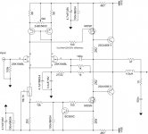
Guys this is the last version -2- int the attechment.
I have this schematics from WidowMaker in the Bulgarian board.
Will be great if anyone can design the PCB for this ,because for me this is the best public version of this great and simple amp.
If anyone can make this version and the PCB- I`am so grateful to him!
Thanks
I have this schematics from WidowMaker in the Bulgarian board.
Will be great if anyone can design the PCB for this ,because for me this is the best public version of this great and simple amp.
If anyone can make this version and the PCB- I`am so grateful to him!
Thanks
Attachments
ZuMbAiU said:..this is the last version ... I have this schematic from WidowMaker in the Bulgarian board. Will be great if anyone can design the PCB for this, because for me this is the best public version of this great and simple amp. If anyone can make this version and the PCB- I`am so grateful to him!
It might be premature to lay this out as a board. A layout is not hard, the work of an evening, but I see a few causes for concern.
Perhaps you might want to change a few values so this has a gain greater than 1. It appears the resistor labelled 22/27 might want to be say 22K for a gain of 45? Just a guess....
The 78L15 needs input bypass caps and output filter caps, but that is a clever current sink design for the input pair.
The very low value resistors in the output stage seem wrong, perhaps the 2R2 should be higher, and they should probably connect to the emitters of the output, not the feedback line,
The VAS current sink will load the VAS at 175ma, a little high, but still not enough to bais on the output transistors and prevent crossover distortion on the output devices.
There does not appear to be any emitter resistors on the output devices, nor any attempt to stablilize bias current (might not matter because there is none, it's "pure class B").
You may want to consider an input low pass filter, and an input DC blocking capacitor.
Overall I see some clever design tricks, but perhaps some further refinements might be needed? Well, good luck with it.
slowhands said:It might be premature to lay this out as a board.
Hardly - a resistor value change does not make the resistor bigger or smaller so it wouldn't fit the board!
...The 78L15 needs input bypass caps and output filter caps, but that is a clever current sink design for the input pair.
It is also a clever voltage reference design for the VAS stage current sink. It should be quite obvious that it would not work as such with the bypass caps. That being said, I would consider replacing it with a different current source as the 78L15 is not known for it's bandwidth, which would be of benefit in this application. Still, people built it and it works, so...
The very low value resistors in the output stage seem wrong, perhaps the 2R2 should be higher, and they should probably connect to the emitters of the output, not the feedback line,
The VAS current sink will load the VAS at 175ma, a little high, but still not enough to bais on the output transistors and prevent crossover distortion on the output devices.
There does not appear to be any emitter resistors on the output devices, nor any attempt to stablilize bias current (might not matter because there is none, it's "pure class B").
2R2 are fine and connected where they should be, so is the VAS current, and no, it should definitely NOT bias the output transistors into class AB as the amp stands now - and for the same reasons, it does not need idle current stabilization.
It seems your hands were rather quick to write up a comment 🙂
It would have been beneficial to read the thread, since you don't seem to recognise a current-dumping configuration (similar to QUAD 405 etc) - the series inductance, 47ohm, 120pF and 1k || 1k form a bridge structure rather typical of a CD amp.
- Home
- Amplifiers
- Solid State
- Death of Gain Clone