Why in DIY project GC case replaced with that "baking pan" ???😕Here an inspiration for a solution for an enclosure/cabinet
Synergy - LM3875 Gainclone Amplifier (Chip Amp)
Not regarded to a technical reason - only regarded the design (the pic looks nice).Why in DIY project GC case replaced with that "baking pan" ???😕
Because I received a lot of PMs regarding this project...
Due to the engagement with my work (yes, the money is not
a good thing, but still works when you need to buy some stuff),
I don't have enough time to spend it with my hobbies. The other
reason is that I already moved to the vacuum team. It is simpler
and long time short circuit at the output is not a big deal at all 😀
Attached is the schematic of DoGC with some little improvements.
Will try to test the offset stability at different ambient temps and
will report the results here ASAP. Thank you!
P.S. Still have some PC boards for this project, PM or mail me if you
have any interest or questions: widowmaker@mail.bg
Attachments
If someone is going away from a Gainclone, why would they pick this particular circuit, there might be better yet simpler circuits out there that outperform Gainclones and this circuit as well..
@metal
I think you are a little too much questioning this circuit.
It has several interesting parts.
And my opinion it is rather simple.
We can not make too simple if we want a good amplifier.
If we do that we run into troubles and sound will not be good.
@widowmaker
Thanks for sharing this circuit once more.
It might bring me back to diyadio.com ....
I have been away for so many years.
🙂
Yes, Lineup, I have missed you.....
You are a great asset to this forum and a good friend to me and many others.
'From one of the coldest places on the planet yet with an creative, feverish mind'.
Ciao,
Hugh
You are a great asset to this forum and a good friend to me and many others.
'From one of the coldest places on the planet yet with an creative, feverish mind'.
Ciao,
Hugh
Thanks AKSA. And adason.
I am troubled with whathas happend to planet10.
But I see he has recovered pretty well.
I see you AKSA are contributing as you always do.
Even with interesting new designs.
Have a good day, both of you.
I am troubled with whathas happend to planet10.
But I see he has recovered pretty well.
I see you AKSA are contributing as you always do.
Even with interesting new designs.
Have a good day, both of you.
Open-loop gain decreases proportionally to frequency. Amplitude of sensed error increases proportionally to frequency. And it uses an interesting mixture of parts.
Long life to Death of Gain Clone!
Long life to Death of Gain Clone!
Let me put some exotic taste (in the attachment) in this very old thread 🙂Open-loop gain decreases proportionally to frequency. Amplitude of sensed error increases proportionally to frequency. And it uses an interesting mixture of parts.
Long life to Death of Gain Clone!
I have also another, less exotic version with bootstrap instead of inductor.
LTSpice shows interesting things (values and pictures) when simulate both
of them. 2SK369 still can be found on ebay, I use factory matched K369s
with Idss 13.5mA from Japan.
I don't like cascode stages, constant current sources and other similar stuff,
that makes some schematics to look let's say cooler, the only exception here
is the current mirror, not because I like it, no, simply there is not enough gain
without it. In other words it is a necessary evil in this schematic with only two
voltage gain stages.
Attachments
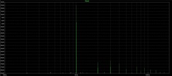
Do you have specific technical reasons for not liking current sources/mirrors or cascodes? Have you built this design? The simulation is not showing any mains harmonics so it looks unbelievably good lol.
If you check the thread from the beginning, you'll see that this is not only "on paper".
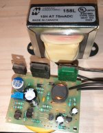
The last version is "on the way", but it is still not ready, for sure I will post some pictures
during assembling.
The last version is "on the way", but it is still not ready, for sure I will post some pictures
during assembling.
Feed forward error correction amp. At least 2 Quad models work on the same principle.
It is invented by Harold S. Black in 1929. Two years earlier, in 1927 he also invented the
negative feedback. My schematic has different settings compared to those Quad amps.
I have about 20 years experience with this design, but usually I make SE class A valve &
hybrid amplifiers.
It is invented by Harold S. Black in 1929. Two years earlier, in 1927 he also invented the
negative feedback. My schematic has different settings compared to those Quad amps.
I have about 20 years experience with this design, but usually I make SE class A valve &
hybrid amplifiers.

- Home
- Amplifiers
- Solid State
- Death of Gain Clone