I very much question the statement that this amp could be made for $5.00 . Buying new MKP caps for this one might come in at about that. The small Fets look difficult to source. Heatsinking anyone ?? Transformers ??
This amp maybe fantastic, but lets calm down the hyperbole a bit, otherwise your going to start to annoy potential builders.
Shoog
This amp maybe fantastic, but lets calm down the hyperbole a bit, otherwise your going to start to annoy potential builders.
Shoog
Shoog said:I very much question the statement that this amp could be made for $5.00 . Buying new MKP caps for this one might come in at about that. The small Fets look difficult to source. Heatsinking anyone ?? Transformers ??
This amp maybe fantastic, but lets calm down the hyperbole a bit, otherwise your going to start to annoy potential builders.
Shoog
I was not talking about those parts, you need them in a GC as well...
But I am curious about heat sinking too. Probably it does not need any, since it is compared to a GC.
Shoog said:When you have compared your amp to at least 5 Gainclones, some with buffers, some without, some with regulated power supplies and some with snubbered powersupplies and even some with SMPS (ala NUUK). When you have done that, and it has conclusively bettered every one with an impartial testing panel - I personally will agree with you that you have killed the Gainclone.
Have you done this yet? If not stop making stupid statements.
I agree.
I still cannot believe that I see so many people generalizing and calling 'GC' to any kind of amp that has a chip inside.
How many different implementations, PCB layouts, PSUs, component choices, topologies can you make with an LM3886 chip, or any other?
I ask this to the thread starter: you show a schematic of your 'DOGC' amp, what about that thing you call a 'GC'?
Also, open the lids of your amps, please, show us a pic.
I have a chip power amp on my main system (chock, horror), and it sounds much better to me than many so-called 'high-end' amps, and you can bring some Krells.
If you call my amp a 'GC' I'll smackah u face. (c) Jocko
😀
Here is a list of costs for parts:
2pcs 2SK301 0.50 euro
2pcs BC560C 0.05 euro
1pcs BC550C 0.03 euro
1pcs IRF9610 IR 0.50 euro
1pcs IRF620 IR 0.50 euro
1pcs BD911 ST 0.60 euro
1pcs BD912 ST 0.60 euro
1pcs 7815 0.14 euro
1pcs 4,7uf WIMA MKP 0.73 euro
1pcs 3300uf/10V FC 0.10 euro
2pcs 100nf WIMA MKS 0.20euro
16pcs Resistors 1% metalfilm 0.60 euro
Total costs: 4.55euro
It's cheaper than the GC 😉
alternative fpr J-fEt
Hello
nice design.
I dont think the designer really wanted to offend the gainclone users, Its just a pun.
What Fet could be used instead of the 2sk301? I didn't even find a datasheet. Maybe a J201 or BF245 or 2n3819?
Greetings
Black
Hello
nice design.
I dont think the designer really wanted to offend the gainclone users, Its just a pun.
What Fet could be used instead of the 2sk301? I didn't even find a datasheet. Maybe a J201 or BF245 or 2n3819?
Greetings
Black
Do you have a PCB design ready? I suppose it will be not unimportant also with this design.
With that prices of parts you could eventually provide a kit package (with a nice pcb perhaps)?
That could make people happy until the Lovoltech JFETs will arrive. 😉
With that prices of parts you could eventually provide a kit package (with a nice pcb perhaps)?
That could make people happy until the Lovoltech JFETs will arrive. 😉
Total costs: 4.55euro
That's plain wishfull thinking m8, for the average DIYer having to buy at the local shop it'll be closer to 45,00 euro .. while a lm1875 can be had at less than 10,00 euro
I think the design is clever and innovative. It almost looks like a Pass design...... and that's high praise indeed.
I would welcome a few words from Widowmaker on how the feedforward works.
The gainclones are all good amps, but I'd expect this would be better in the clarity and soundstage stakes. You could build it out (with some difficulty) for more power, too.
A pcb would not be that critical, either. Note this amp does not require lag compensation. This is a huge plus.
Cheers,
Hugh
" ...they sound much more better ... "
..., but many others sounds still better... All is relative, Carlos....Is funny, this neverending searching for some simple and " deadline " solution, certainly " ASAP " cheap....Space isn't simply and somewhere is siletly smiling God....
..., but many others sounds still better... All is relative, Carlos....Is funny, this neverending searching for some simple and " deadline " solution, certainly " ASAP " cheap....Space isn't simply and somewhere is siletly smiling God....
this days I'll publish on my site schematic for Preamp ,and his name (oficiall!) will be
"Exactly Your GC (also Inverted!) and your Pass Amp and your KSAanynumber KILLER!"
weight of supply is cca 15KG ,and main box (with few active devices) have around 8KG
Output power is somewhere in range of 0,8W/ 2 to 600 OHMS/ch..........
then you can say anything you want about my preamp-it's still killer of your amp!
are you (some )ppl on hard weed this days
?
arguing about name of amp-and man just show that he have sense for funny side of life?
back to weed, and please sit somewhere by the river.........without words
AKSA
When I asked how this feedback thing works, in another thread,
widowmaker refered to an article
"Current Dumping Audio Amplifier" by P.J. Walker
It is found here: http://home.jps.net/~shiloh/currentdumping.pdf
It is also found along with other information in this info page about Quad 405:
Quad 405 & 405-2 Current Dumping Audio Amplifier
http://home.jps.net/~shiloh/
P.J. Walker
An externally hosted image should be here but it was not working when we last tested it.
Hi David Lumanauw
I only wanted to say that it does not resamble forward error correction. The output stage is transconductance 'current dumpers'. These two terms do mix up sometimes because both were (first?) used in quad405.
I only wanted to say that it does not resamble forward error correction. The output stage is transconductance 'current dumpers'. These two terms do mix up sometimes because both were (first?) used in quad405.
It is worth downloading the Quad 606 schematic diagram from the second link in lineup's post above. It shows very clearly the bridge arrangement discussed in P. J. Walkers writeup. I believe that if one looked at what this bridge actually does, one would successfully argue that it is a form of feedforward error correction.
It may also be interesting to trya pair of small MOSFETs (like 2N7000, BS107 or BS170) instead of the input FETs. Although these have a higher input capacitance, the input stage sees relatively small changes in Vd so it should not be an issue. The MOSFETs have a higher transconductance, higher Vdsmax, higher power dissipation and can work at a higher current, which can be used to advantage with the MOSFET driver pair. A pair of decent beta sustained transistors at the output could also help things, but then the price would be quite a bit higher than a chipamp!
It may also be interesting to trya pair of small MOSFETs (like 2N7000, BS107 or BS170) instead of the input FETs. Although these have a higher input capacitance, the input stage sees relatively small changes in Vd so it should not be an issue. The MOSFETs have a higher transconductance, higher Vdsmax, higher power dissipation and can work at a higher current, which can be used to advantage with the MOSFET driver pair. A pair of decent beta sustained transistors at the output could also help things, but then the price would be quite a bit higher than a chipamp!
Re: " ...they sound much more better ... "
I'm trying to figure out what do you mean, really.
I'm not saying there's not better, but it is not so easy as you think.
But what am I talking about? Take a plane to Lisbon and come on listen.
Bring one of your 'ultra-complex' designs with 1Km signal path and 3000 solder joints.
You don't get it, do you?
Upupa Epops said:..., but many others sounds still better... All is relative, Carlos....Is funny, this neverending searching for some simple and " deadline " solution, certainly " ASAP " cheap....Space isn't simply and somewhere is siletly smiling God....
I'm trying to figure out what do you mean, really.
I'm not saying there's not better, but it is not so easy as you think.
But what am I talking about? Take a plane to Lisbon and come on listen.
Bring one of your 'ultra-complex' designs with 1Km signal path and 3000 solder joints.
You don't get it, do you?
Hi, Darkfenriz,
I still cannot see any "Error Correction" process inside this DOGC. I don't understand the theoritical process of "Current Dumping", why it needs 4 component bridge (I think this should work without 120pF+4.5uH, but don't know about the stability without these 2 components), but as I see it, the finals (911-922) works like a "switch". 911-922 won't work until the drop at 47ohm (disregarding 2R2) becomes 0V6 or 911-922's VBE drop. It is IRF620-9610 who pushes the 47ohm.
This makes 911-922 will always be turnon-turnoff depending the drop at the 47ohm, +/- or-/+ depends on IRF's are pushing or pulling current from the 47ohm.
This process is similiar to Circlotron's "Current Booster", you can look here somewhere.
One interesting thing about this design is that DOGC doesn't have VBE multiplier or any biasing scheme. This could be a good thing.
BTW, what's the bias for the differential? Is it 15V/1k8 = 8.3mA? What's the good thing about using 7815 for constant current?
The voltage drop across each 2R2 resistors is 0.330V. (150mA)
so about +-0.3V across 47 Ohm and BD911/912 turns on.
Gives like +- 6mA output before this happen.
I guess the inductor plays an important part in this design.
so about +-0.3V across 47 Ohm and BD911/912 turns on.
Gives like +- 6mA output before this happen.
I guess the inductor plays an important part in this design.
Thanks Lineup, appreciate the explanation.
BUT, this approach means that the 911/912 are always turning on and off - this is normal of course in current dumping - but it takes us back to the same old crossover problem.
David,
The 7815 is indeed supplying 8.32mA through the 1K8 resistor and is used to confer high PSRR and strong current regulation. BUT, it is also supplying the current through the bipolar collector which biases the driver stage. The 100nF cap damps any variations, decouples the two circuit blocks. I'd say this additional current was around (15 - 4)/15K, or 0.7mA, so that the total current supplied through the regulator to the LTP is just over 9mA. Actually, this part of the circuit is particularly economical and clever.
Cheers,
Hugh
aksa
"Actually, this part of the circuit is particularly economical and clever."
i have a few 7812 1A devices i want to sell off, you could use it
instead with some adjustments,if your interested send me an email
cheers
"Actually, this part of the circuit is particularly economical and clever."
i have a few 7812 1A devices i want to sell off, you could use it
instead with some adjustments,if your interested send me an email
cheers
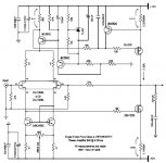
Personally
I like the Single End Class A - 8W/4 Ohm - +-12V supply
by widowmaker better, see CIRCUIT below.
I think it has greater potential to become a very popular project.
What I should change is to use 2SK389 instead of more hard to find SJ109 in input.
Even 2SK389 is not easy to get a hold on everywhere.
So I would make 2 separate, but closely match single JFETs, an option.
TL431 and BC550/BC560 is no problem to find.
The output MOSFETs 2SK1529/2SJ200 is not everywhere
but can be found most countries??
Complementary output MOSFET pair are biased 2.32 Ampere for 8 Watt into 4 Ohm speakers.
A nice little class A project!
What would be a proper Power Supply for good +-12 V DC ??
Attachments
- Home
- Amplifiers
- Solid State
- Death of Gain Clone