Yes it is. Simply download and test my Microcap12 circuit file [ https://www.patreon.com/posts/60580885 ] and you will see only several microvolts DC output offset [ https://c10.patreonusercontent.com/4/patreon-media/p/post/64958853/4e3bb8ef00ec42f4bd07663deeb42f06/eyJxIjoxMDAsIndlYnAiOjB9/1.jpg?token-time=1660953600&token-hash=wbYAnpmA35FwAhB0ZRlQjzJtwDKbNaamVIeCMcg3QTg= ] . more detailed here https://www.patreon.com/posts/1-5-mikrovolta-v-64958853Seems that DC servo is used as virtual ground for biasing resistor of the CCS at SE output stage. Varying current through diodes provides enough Vbe variation on CCS, to compensate for any change at the output.
Attachments
Last edited:
So paying a premium for 10uV offset opamp is money wasted for me.
Jan
OPA1656 has 1 mV offset and costs 5$, I propose OPA192 which has 5 uV offset and 3.5$. OPA192 has 280 times better offset/$ ratio ;-} Which do you prefer ? ;-)
OPA1656 was not really a candidate for DC servo. Thread title was set by moderator, while making a thread split from OPA1656 thread, where some questions about servo circuits were asked and discussion followed.OPA1656 has 1 mV offset and costs 5$, I propose OPA192 which has 5 uV offset and 3.5$. OPA192 has 280 times better offset/$ ratio ;-} Which do you prefer ? ;-)
I see, but others also are not competitors to OPA192 @ DC servo, isn`t it? Let`s make a table with offset/$ ratio 😏OPA1656 was not really a candidate for DC servo. Thread title was set by moderator, while making a thread split from OPA1656 thread, where some questions about servo circuits were asked and discussion followed.
Well I can see this is important to you.
Would you consider the ADA4000? About a buck?
ADTL082, 50 cents?
Jan
Would you consider the ADA4000? About a buck?
ADTL082, 50 cents?
Jan
Yes, OA192 is good. But ..Let`s make a table with offset/$ ratio 😏
As already pointed out, there is something called “optimum design”. I don’t know of any loudspeakers or headphones with requirement, or that would benefit from only several uV DC offset, not to mention audio amplifiers.
Simple offset/price ratio is not good FOM.
How about LF noise? OPA192 has 100 nV/rtHz at 10 Hz while OPA1641 has 8 nV/rtHz.
Attachments
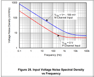
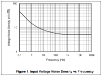
OPA192 has 30. At 10 Hz, which is lagely reduced with normal integrator time constant to negligible levels.How about LF noise? OPA192 has 100 nV/rtHz at 10 Hz while OPA1641 has 8 nV/rtHz.
How much offset can you add at the amplifier input before the DC loop fails? You can just put a DC source in series with the gate of one input JFET and do a DC sweep.Yes it is. Simply download and test my Microcap12 circuit file [ https://www.patreon.com/posts/60580885 ] and you will see only several microvolts DC output offset [ https://c10.patreonusercontent.com/4/patreon-media/p/post/64958853/4e3bb8ef00ec42f4bd07663deeb42f06/eyJxIjoxMDAsIndlYnAiOjB9/1.jpg?token-time=1660953600&token-hash=wbYAnpmA35FwAhB0ZRlQjzJtwDKbNaamVIeCMcg3QTg= ] . more detailed here https://www.patreon.com/posts/1-5-mikrovolta-v-64958853
Don't blaim the moderators, as Jan did consider using an OPA1656 for a DC servo.OPA1656 was not really a candidate for DC servo. Thread title was set by moderator, while making a thread split from OPA1656 thread, where some questions about servo circuits were asked and discussion followed.
Because I had it laying around and needed full DM input. Not based on specific requirements.
It's really too expensive for that.
Jan
It's really too expensive for that.
Jan
I see, that makes sense.
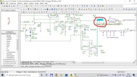
By the way, one of Nick's diodes became a resistor:


That seems more logical, as D1-R33 and Q4-R12 now form a current mirror. Nevertheless, I'm still curious about the control range.
By the way, one of Nick's diodes became a resistor:
That seems more logical, as D1-R33 and Q4-R12 now form a current mirror. Nevertheless, I'm still curious about the control range.

Ideal capacitors generate no noise, non-ideal ones have loss resistances that generate thermal noise. Maybe they also have shot noise or excess noise related to their leakage if there is a DC bias voltage across them - I'm not at all sure about that, but I can't think of any law of physics that would forbid it.Low LF noise could be a factor, not sure because the integration cap has a higher impedance at LF and thus also generates noise.
I haven't done the sums, maybe no factor, maybe dominates. And what about the usual 1M R?
Jan
Capacitors used in DC servos are usually good quality capacitors with negligible leakage, so what matters are loss resistances. Suppose you have a high-quality 100 nF capacitor with a tan(delta) of 0.1 %, and let's assume that tan(delta) applies at all frequencies (I would actually expect it to get better at very low frequencies). The reactance at 20 Hz is 79.5775 kohm, so the ESR would then be 0.1 % of that: 79.5775 ohm, resulting in 1.135 nV/sqrt(Hz) of noise voltage at 20 Hz and 20 degrees Celsius, far less at higher frequencies.
The usual 1 Mohm resistor injects 0.12724 pA/sqrt(Hz) of noise into the integrating capacitor. Again assuming 100 nF, that's 10.125 nV/sqrt(Hz) at 20 Hz. It goes down inversely proportionally with frequency and with the capacitance of the integrating capacitor.
Servos are only in the audio path below 1hz
Usually below 0 .01 hz.
So they are not actually in the audio path.
Tl071 works well here
Usually below 0 .01 hz.
So they are not actually in the audio path.
Tl071 works well here
The main advantage of such a DC servo (vs servo output to the input stage) is not adding noise. It is very important for lov-level preamps. I have seen it in Microcap clearly. And don`t worry about control range - OPA192 is rail-to-rail and its output range is fully enough to control Q4 current from 0 to twice of normal.I see, that makes sense.
By the way, one of Nick's diodes became a resistor:
View attachment 1078475
View attachment 1078477
That seems more logical, as D1-R33 and Q4-R12 now form a current mirror. Nevertheless, I'm still curious about the control range.
How much input offset does that correspond to? Is that more or less than the maximum VGS mismatch of the JFET pair?
If you need only a small control range and are worried about noise, you can also use a voltage divider to attenuate the integrator's output voltage. That seems more predictable to me. In either case, you have to check whether the worst-case offset and the maximum expected deep subsonic input signal can drive the DC loop into clipping.
By the way, an issue you also have when putting a DC loop around an RIAA amplifier is that if there is any loop gain left at audio frequencies, the loop will shift the equalization poles (but not the zeros). You can correct for that, but it complicates the calculations.
Last edited:
I use a very low offset opamp on my X-Altra MC input stage. Because the delta Vbe between the two input transistors can be a few mV and the output of the typical MC cart is just 200-500 uV at 3-10 Ohms Rgenerator, you really don't want those kind of large DC current offsets flowing in the cart coil. So I used an OPA2188 to servo the input offset down to +- a few uV (+-6uV typical, +-25uV max). So indeed, for these kinds of applications you do need ultra low offsets. But for a power amp output offset, a few mV is really neither here nor there. A top grade TL071BC specified Vos at 5mV over the full operating temp range (0 to 70C) and Vos drfit at 18uV/C. This is absolutely fine for any audio power or preamp amp you care to name - no point in wasting hard earned $ on stuff that is not needed.
🙂
🙂
That is a very nice looking device 👍Self advocates the JFET input opamp TL051 (USD 0.71 @ qty=1) whose input offset voltage is 1.5 mV . The "A suffix" variant is better but a lot more expensive.
_
- Home
- Amplifiers
- Solid State
- DC Servo using the OPA1656 CMOS Opamp