
Moderation edit... thread split from here:
https://www.diyaudio.com/community/...ormance-cmos-audio-op-amp.335416/post-7084083
---------------------------------------------------------------------------------------------------
I understand, but it is not for the direct audio circuit. Its in the servo and should be OK for that.
The 1642 is unobtanium (SOIC08).
You have some for sale? ;-)
Jan
Last edited by a moderator:
I think what I saw was the output jumping to the rail dumping a large current through the integration cap back to the input.
Works with G=1 in that situation.
But I haven't checked it in LTspice yet.
Jan
Works with G=1 in that situation.
But I haven't checked it in LTspice yet.
Jan
What about OPA2140, the non-audio / general purpose instrumentation version of OPA1642? Mouser has a bunch of stock for the SOIC-8 package. I don't know all the differences between the two parts, OPA2140 is obviously trimmed for lower offset and therefore more expensive, but no idea if there are any other differences and what they are.I understand, but it is not for the direct audio circuit. Its in the servo and should be OK for that.
The 1642 is unobtanium (SOIC08).
You have some for sale? ;-)
Jan
That's a very good tip! It looks quite useable, although, again, they are ambiguous on the differential input voltage - they don't mention it.
They give the CM input range in the abs max table, and somewhere else they mention that each input can go up to the rails.
Maybe I should write a documentation report.
Jan
They give the CM input range in the abs max table, and somewhere else they mention that each input can go up to the rails.
Maybe I should write a documentation report.
Jan
Please forgive what is likely a dumb question, but why use such a high grade op-amp in a servo?
I ask since so far I am just using TL071/TL072 types for servos. As an example, I built a measurement LNA based upon the Douglas Self MC design and it just uses a TL071 to servo the offset from the three parallel LN transistors and NE5534 (or OPA228) amplifier stage.
Why use a much more expensive OPA1641/42/OPA2140 for a servo?
Standard answer is: because the servo is in the signal path. Cordell's book section 10.3 of 2nd edition (section 8.3 of 1st edition) says
The Servo is in the Signal Path
The DC servo in Figure 10.5 is in the feedback path with modest gain at low frequencies. As such, the DC servo is in the signal path of the amplifier, and its performance can affect sound quality. The fact that it is injecting a signal at the input stage gives it the opportunity to inject noise and distortion into the signal path. This can affect the quality of the audio signal. ... For this reason, audio-grade opamps should be used for the DC servo's integrator ...
Jan, looks like TI have stock of the opa1642, also in so8. TI sell direct online worldwide, usually at the best prices....
Which is why Servo circuits usually are also low pass filters or additionally filtered.Standard answer is: because the servo is in the signal path. Cordell's book section 10.3 of 2nd edition (section 8.3 of 1st edition) says
The Servo is in the Signal PathThe DC servo in Figure 10.5 is in the feedback path with modest gain at low frequencies. As such, the DC servo is in the signal path of the amplifier, and its performance can affect sound quality. The fact that it is injecting a signal at the input stage gives it the opportunity to inject noise and distortion into the signal path. This can affect the quality of the audio signal. ... For this reason, audio-grade opamps should be used for the DC servo's integrator ...
I see. I was not expecting much impact due to the ~ Hz level integrator time constants and >> 10kOhm load on the output of the TL071/72. Given those parameters and the TL071/72 performance/gain/PSRR/CMRR/distortion/etc at those frequencies I thought the TL071/72 would be very safe.
What TL071/72 performance characteristic might show up as a measurable or perceivable limitation? What sort of back-of-the-envelope calculation could show/quantify the concern?
After all the Douglas Self MC based 60 dB LNA design achieves quite impressive noise and distortion performance for only one NE5534, one TL071 servo and three TO92 transistors. (So after building that LNA I later used the TL071/72 in other servos without really much of a second thought.) I don't have Cordell's book. (Perhaps I should put that on the shopping list?) Does it have calculations or measurements that dig deeper into this topic?
Anyone besides me ever tried connecting the output of a servo opamp to a preamp input and listened to what it sounds like? Because that's what's going to be mixed back in with the music...
To what extent the performance of the servo op-amp matters depends entirely on the circuit.

I did (and measured THD)... unless the opamp is totally unsuited (741 ;-) or the integrator cap is utter crap there is nothing to be seen/heard.Anyone besides me ever tried connecting the output of a servo opamp to a preamp input and listened to what it sounds like? Because that's what's going to be mixed back in with the music...
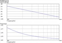
With -63 dB and -176 degrees at the output of the integrator (at 10 Hz) I am not expecting anything beyond a very small gain reduction. (TL071/72, 1% metal film, PP capacitors and regulated supplies.)
In other words I am expecting a heavily attenuated/filtered but very low distortion and low noise signal to be applied as negative feedback. At these low frequencies and high load resistances I expect the distortion to be exceedingly low.
In other words I am expecting a heavily attenuated/filtered but very low distortion and low noise signal to be applied as negative feedback. At these low frequencies and high load resistances I expect the distortion to be exceedingly low.
Attachments
The servo works only as a low pass (integrator actually) thanks to its loop gain at high(er) frequencies that provide the feedback. So I can understand that with not-so-hot opamps there will be signal and/or distortion at the servo output.
But as Marcel noted, it depends a lot on the circuit and how 'aggressive' the servo is.
Note that with an amp with -100dBV distortion, an output of 10uV of the servo will have the same level.
Jan
But as Marcel noted, it depends a lot on the circuit and how 'aggressive' the servo is.
Note that with an amp with -100dBV distortion, an output of 10uV of the servo will have the same level.
Jan
Jan,The servo works only as a low pass (integrator actually) thanks to its loop gain at high(er) frequencies that provide the feedback. So I can understand that with not-so-hot opamps there will be signal and/or distortion at the servo output.
But as Marcel noted, it depends a lot on the circuit and how 'aggressive' the servo is.
Note that with an amp with -100dBV distortion, an output of 10uV of the servo will have the same level.
Jan
It would seem to be silly to not have attenuation on the Servo opamp output. As the greatest correction required should only be in the millivolt range I would expect at least a 100 to 1 reduction along with a low pass noise filter. It seems easy to get a multi-pole filter function with a simple filter on both input and output of the Servo amp.
Sure, that's smart, and I assume that's one of the things Marcel implied.
But you need to be carefull with additional low pass filtering of the servo output.
Before you know it you have a 2nd order system and LF oscillations.
You should make sure that the integrator time constant and the additional filter TC are sufficiently apart.
Jan
But you need to be carefull with additional low pass filtering of the servo output.
Before you know it you have a 2nd order system and LF oscillations.
You should make sure that the integrator time constant and the additional filter TC are sufficiently apart.
Jan
It's a matter of preference, but I wouldn't want to design a DC servo such that a large subsonic input signal can clip the op-amp and cause offset if the clipping is asymmetrical.Jan,
It would seem to be silly to not have attenuation on the Servo opamp output. As the greatest correction required should only be in the millivolt range I would expect at least a 100 to 1 reduction along with a low pass noise filter. It seems easy to get a multi-pole filter function with a simple filter on both input and output of the Servo amp.
- Home
- Amplifiers
- Solid State
- DC Servo using the OPA1656 CMOS Opamp