The TL071 is fine for the application. FET inputs make it ideal for integrator use and the offsets are low enough for power amp use.I like Marcel's circuit plenty, well filtered and a belt'n'suspenders approach. I guess the biggest question is why the TLO7x? It's hardly what anyone would call a precision opamp for the location. Is it the PDIP factor? (blah, SO is easy) I can't imagine it's cost as jumping up even $1/channel is not changing anyone's BOM substantially.
Edit -- looks like the interest is around rail-to-rail input?
E.g. there's the OP07C in PDIP.

Agree. There are several trade-offs involved in the design of a DC servo. In my designs, I first ensure that the servo can correct the maximum expected amplifier offset while the amplifier is outputting a full-scale signal at the lowest expected frequency. I prefer that the servo's closed loop bandwidth be ~0.2 Hz. This is a design choice. If these requirements can be met while also accommodating some input offset, without undesirable noise or distortion injection, so much the better. To address your concern, I monitor the servo's output voltage and disconnect the speaker if it is nearing the opamp's limits.It's a matter of preference, but I wouldn't want to design a DC servo such that a large subsonic input signal can clip the op-amp and cause offset if the clipping is asymmetrical.
I think the trick is the very large ratio of your R6 to R2//R7 and the fact that R6C3 >> (R2//R7) C2. As a result, there is almost no difference between the pole that C2 causes in the loop gain and the zero it causes in the transfer, so you get a near perfect cancellation.Hello Marcel
There is no frequency aberration.
Edit: sorry, this is complete nonsense. I thought the pole couldn't move much with feedback because of the zero right next to it, but that is wrong because it's not a zero in the loop gain.
Last edited:
I have used the TL071, but I prefer the OPA132 or, if I am feeling wealthy, the OPA627. They have better AC and DC performance. With either of these, there is no need for a filter after the integrator (assuming the gains are correct).The TL071 is fine for the application. FET inputs make it ideal for integrator use and the offsets are low enough for power amp use.
It's this in combination with the fact that the pole that C2 causes kicks in at a frequency well above the DC loop bandwidth, where the DC loop has practically no loop gain left, so the pole doesn't shift much after all.I think the trick is the very large ratio of your R6 to R2//R7 and the fact that R6C3 >> (R2//R7) C2. As a result, there is almost no difference between the pole that C2 causes in the loop gain and the zero it causes in the transfer, so you get a near perfect cancellation.
Edit: sorry, this is complete nonsense. I thought the pole couldn't move much with feedback because of the zero right next to it, but that is wrong because it's not a zero in the loop gain.
Thank you, Ultima Thule! Sorry all; I am new here. I will try to remember the white background next time. I checked my preview and it was fine, but then my theme is not Dark. Thanks for the education!The picture in post #45 has a poor contrast for those of us having forum theme color set to Dark due to a transparent background.
@Bonsai What's the ratio of Rf to Rg?I'm doing it like this. On a CFA amp , the inverting input is low z in so its not a convenient place to inject a servo signal. This works well. U1 is a TL071.
View attachment 1076428
Servo opamp have his problems ,hear between the same opamp maked in Spain or Mexico or Taiwan 😀😀😀🥴.
There is no performance difference between any operational amplifier and DC server circuit.
It's not worth wasting time.
It's not worth wasting time.
Purchasing op-amps from AliExpress, aren’t you? 😉Servo opamp have his problems ,hear between the same opamp maked in Spain or Mexico or Taiwan 😀😀😀🥴.
If you refer to sound differences observed by replacing op-amp in a properly designed servo circuit, then this is above ordinary human hearing abilities.
Absolutely incorrect.There is no performance difference between any operational amplifier and DC server circuit.
It's not worth wasting time.
In example, cutoff frequency of discussed inverting LPF circuit is determined by impedance in parallel with C2. So, internal op-amp input to output impedance affects desired low pass frequency, which can’t be precisely calculated, rather estimated or measured.
Attachments
You dont hear it,thats is the problemThere is no performance difference between any operational amplifier and DC server circuit.
It's not worth wasting time.
Last edited:
After 30 years ago after Twenty years ago after ten years ago,sold i different opamp buy by importer ,not by AliPurchasing op-amps from AliExpress, aren’t you? 😉
If you refer to sound differences observed by replacing op-amp in a properly designed servo circuit, then this is above ordinary human hearing abilities.
Last edited:
I've run it through a pole-zero extraction program assuming Rg = 27 ohm. It finds a zero at -1012.13 rad/s, as expected, and a closed-loop pole at -1012.15 rad/s, resulting in a loss of bass of less than 0.0002 dB. No wonder you didn't see any aberration!1k for Rf and between 22 to 33 for Rg
Much to my surprise, it reported the pole to be at -1012.15 rad/s both in open loop and in closed loop. Looking at the root locus and zooming in a lot, I see that it does shift to the left when the loop is closed, but by such a small amount that the value rounded to six digits remains the same.
I started to understand that when I looked at the loop gain. Thanks to the filtering effect of both the integrator and the input capacitor, the loop gain drops with a second-order slope and is of the order of 1.1*10-6 at the frequency where the third pole kicks in.
Thanks, it has been very interesting!
Is it? I have never found such an effect in measurement.Absolutely incorrect.
In example, cutoff frequency of discussed inverting LPF circuit is determined by impedance in parallel with C2. So, internal op-amp input to output impedance affects desired low pass frequency, which can’t be precisely calculated, rather estimated or measured.
Don't guess. You only need to take a few minutes to measure once.
I am on e405 mod (L9 circuit)
Use njm4580, ne5532, tl072, ad8620.
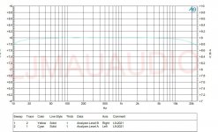
The frequency response is completely coincident. There is no difference.
Attachments

After 30 years ago after Twenty years ago after ten years ago,sold i different opamp buy by importer ,not by Ali
At least in the DC server circuit. Njm 4580 is very good.
Don't waste money buying any operational amplifiers. meaningless.
They have the same frequency response. Distortion is the same.
My operational amplifier comes from Ti BB ns company as a gift.
I have almost all operational amplifiers. There is no practical difference between them.
Attachments
Don't feed the troll.Absolutely incorrect.
In example, cutoff frequency of discussed inverting LPF circuit is determined by impedance in parallel with C2. So, internal op-amp input to output impedance affects desired low pass frequency, which can’t be precisely calculated, rather estimated or measured.
Jan
- Home
- Amplifiers
- Solid State
- DC Servo using the OPA1656 CMOS Opamp