The resistor would let some DC through.
If it's a high value it might just be a discharge resistor. (But that wouldn't be needed unless the diodes fails open.)
Lower values might be some worst case scenario.
If it's a high value it might just be a discharge resistor. (But that wouldn't be needed unless the diodes fails open.)
Lower values might be some worst case scenario.
The resistor would let some DC through.
If it's a high value it might just be a discharge resistor. (But that wouldn't be needed unless the diodes fails open.)
Lower values might be some worst case scenario.
It was 33R.
I saw this variation on the circuit. R1 is a 5W+ power resistor and C3 is a film cap.
Is their purpose to add some worst case scenario protection for the diodes?
And do you think they are are worth adding to the circuit?


The resistor serves no purpose, mention one!
Rod Elliott's design includes a resistor which I will name "R99", between the midpoint of the bridge and the midpoint of the series capacitors. Curiously he sets the value of R99 to be 100 Megohms. Does anybody have a recommendation for a lower value of R99? What's so great about 100 Megohms? Why not 10K ohms?
_
_
Attachments
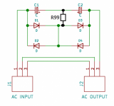
My guess is that R99 is to help Spice converge; without this there is a floating circuit node, at least for DC if the cap model omits leakage.
In real life R99 merely needs to be high compared with the capacitor reactance, so that it does not very much, but perhaps not too high so that it can set the mid-cap potential.
In real life R99 merely needs to be high compared with the capacitor reactance, so that it does not very much, but perhaps not too high so that it can set the mid-cap potential.
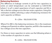
One way to choose the value of R99 is suggested on page 13 of Cornell Dubilier's Aluminum Electrolytic Capacitor applications guide which I have excerpted below.
Since I am using 10,000uF capacitors rated for 10V operation, I will choose Vm=6.3 volts as the maximum I permit across either capacitor due to the difference in leakage currents between the two series capacitors. 6.3 volts is comfortably below the capacitors' 10 volt rating; I prefer to have a safety guardband.
Since the rated maximum forward voltage of my diodes (at 50 amperes of forward current!) is 1.1 volts, and I've got two diodes in series, I will choose Vb=2.2 volts as the "bus voltage across the two series capacitors".
Plugging these numbers into Cornell Dubilier's equation
_
Since I am using 10,000uF capacitors rated for 10V operation, I will choose Vm=6.3 volts as the maximum I permit across either capacitor due to the difference in leakage currents between the two series capacitors. 6.3 volts is comfortably below the capacitors' 10 volt rating; I prefer to have a safety guardband.
Since the rated maximum forward voltage of my diodes (at 50 amperes of forward current!) is 1.1 volts, and I've got two diodes in series, I will choose Vb=2.2 volts as the "bus voltage across the two series capacitors".
Plugging these numbers into Cornell Dubilier's equation
- R = ( (2*6.3) - 2.2 ) / (0.0015 * 1E4 * 2.2)
- R = (10.4) / (33)
- R = 0.32 Megohms
_
Attachments
Last edited:
The problem is, I like R99. I intend to use it. I am attempting to learn whether anyone has a better idea than I do, how to choose an acceptable range of values for it. Rod Elliott says 100 Megohms to Infinity ohms without any justification. Member DF96 thinks R99 >> 1/(2*pi*f_mains*C) "but not too high". Presumably Rod Elliott's 100 Megohms is too high. Member peranders appears to suggest R99=Infinity but doesn't say what might go wrong if R99=10K.
The caps have leakage so when you put AC through them you won't unhealthy charges. You don't need bleeder resistors either since you work with so small voltages. In this application this resistor serves no purpose.
The problem is, I like R99. I intend to use it. Its purpose is to make me happy when it is present. The idea of using the diodes as extra additional leakage mechanisms, pleases me. You of course are free to choose R99=Infinity if you wish.
Will not a DC offset cause one of the caps to be reverse biased, whether or not a resistor is present ?
Balancing makes sense in series connected caps (caps connected to make a higher voltage device), but I'm not so sure it does anything here.
Balancing makes sense in series connected caps (caps connected to make a higher voltage device), but I'm not so sure it does anything here.
They will get -1 V and then +1V with 50 or 60 Hz speed but nothing bad happens in this connection.
The diode leakage will increase nicely at the time when a 50Apk half sine or more passes through the die.
But wouldn't that be classed as AC. Plus and then minus @ 50/60 Hz.
I thought the DC appeared as a change in the symmetry of the pos vs neg half cycles of the mains. That would give a constant DC voltage as measured end to end across the series caps. However you connect the caps, surely one will always be reverse biased. If the offset on the mains changes polarity then the other cap in the series chain becomes the one that is reversed biased.
Although the voltages are small, a 1 volt reverse bias is a large percentage of say a 6.3 volt cap.
Will not a DC offset cause one of the caps to be reverse biased, whether or not a resistor is present ?
Well, sort of.
Both caps alternate between forward biased and reverse biased. However thanks to the DC offset, one of the caps spends most of its time forward biased and the other cap spends most of its time reverse biased. As the Cornell Dubilier app note linked in post #166 indicates, reverse biasing isn't necessarily harmful until the reverse voltage exceeds ~1.5 volts.
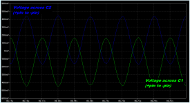
Simulation below. Offset was introduced by plugging in a (simulated) hair dryer with half wave rectifier, into the same (simulated) mains circuit as audio equipment including (simulated) mains DC blocker. The half wave rectifier resulted in a distorted sinewave fed to the audio equipment.
The really interesting thing to do in simulation, is plot the current flowing in resistor R99. Try it and exclaim "Eureka!".
Oh by the way, if you build a simulation, be sure to plot the current in all four diodes. If the diode currents don't fall away to zero after ~ 100 simulated seconds, that means you've got too much asymmetry / DC offset ... more than 2 x Vdiode. Crank down the influence of the hair dryer and try again.
_
Attachments
Last edited:
I have built about a dozen blockers. Just a warning. If you unplug a blocker which has been pulled out of a live wall socket and stick your finger across the exposed plug pins you will get a shock. The charge leaks away in seconds but if you grab the exposed end quick enough you will get a belt.
I have built about a dozen blockers. Just a warning. If you unplug a blocker which has been pulled out of a live wall socket and stick your finger across the exposed plug pins you will get a shock. The charge leaks away in seconds but if you grab the exposed end quick enough you will get a belt.
Put a 1 meg resistor across live and neutral.
They will get -1 V and then +1V with 50 or 60 Hz speed but nothing bad happens in this connection.
You can reverse bias an electrolytic up to about 1.5 volts.
Put a 1 meg resistor across live and neutral.
Even 100K would be fine. I have just sold another blocker but on delivery I must warn the new owner.
I'll suppose you have caps in parallel also because it's hard to feel voltages under 50 V.I have built about a dozen blockers. Just a warning. If you unplug a blocker which has been pulled out of a live wall socket and stick your finger across the exposed plug pins you will get a shock. The charge leaks away in seconds but if you grab the exposed end quick enough you will get a belt.
- Home
- Amplifiers
- Power Supplies
- DC blockers and mains filters