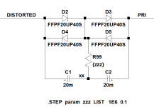
The really interesting thing to do in simulation, is plot the current flowing in resistor R99. Try it and exclaim "Eureka!".
Eureka ! Well I just created a brown noise generator 😀 This is the current in your resistor.

Very interesting indeed. I set my sim up to be able to try different things. You can certainly see the effect of the blocker on the transformer currents, one running on raw mains and one on 'DC blocked' mains.


Mooly, before you try the experiment, make a prediction: what if anything will be different when you simulate your mains DC blocker feeding the primary of a power transformer, whose secondary drives a full wave bridge rectifier and 10,000 microfarad + 0.03 ESR filter capacitor with 1 ampere load? I.e. when the AC current flowing in your C1,C2 6800uF blocking caps is non-sinusoidal thanks to rectifier bridge refilling the ripple troughs in the secondary circuit.
And now that you've seen the current waveform flowing in R99 for both the sinusoidal and non-sinusoidal case, what resistance value do you recommend for it?
And now that you've seen the current waveform flowing in R99 for both the sinusoidal and non-sinusoidal case, what resistance value do you recommend for it?
A predication (haven't tried it, simulation is on a different PC to this one) so let me think.
So 10,000uf, 1 amp and lets say at a rail voltage of 50 volts. 50 watts load current, primary current could be around 0.25 amps give or take for 240 volt mains. 6800uF will have around 0.5 ohms xC @50 Hz. Voltage across and current through the caps is 'not a lot', and way below what would cause them (edit... them = the diodes) to conduct, but that doesn't account for the low conduction angle of the bridge. That's probably going to increase things by a factor of what... five to ten maybe. So that would now bring the diodes into play.
So the resistor. I honestly don't know without trying it. I would guess that making it low (say below 1k) might see a reduction in any unwanted harmonic content in the primary current. Make it to low and you start to negate the effectiveness of the caps.
That's all just quickly thinking aloud.
What's wrong with R99 = zero ohms?
You have observed I = 0; thus the voltage (=I*R by ohm's law) is also zero. If the voltage between node A and node B is zero, what's the harm in shorting nodes A&B together?
You have observed I = 0; thus the voltage (=I*R by ohm's law) is also zero. If the voltage between node A and node B is zero, what's the harm in shorting nodes A&B together?
Last edited:
lowered limit (from ~1.4v to ~0.7v) on the max (forward & reverse) voltage seen by caps.
mlloyd1
mlloyd1
You have both of the caps oriented in the same direction. You should turn around one of them.Eureka ! Well I just created a brown noise generator 😀 This is the current in your resistor.
View attachment 552758
Very interesting indeed. I set my sim up to be able to try different things. You can certainly see the effect of the blocker on the transformer currents, one running on raw mains and one on 'DC blocked' mains.
View attachment 552759
View attachment 552760
What's wrong with R99 = zero ohms?
You have observed I = 0; thus the voltage (=I*R by ohm's law) is also zero. If the voltage between node A and node B is zero, what's the harm in shorting nodes A&B together?
Just trying that in my simulation from this morning and it has the surprising effect of actually lowering the average DC in the primary slightly... hmmm !
lowered limit (from ~1.4v to ~0.7v) on the max (forward & reverse) voltage seen by caps.
mlloyd1
It also makes each cap truly polarity sensitive for any given offset.
You have both of the caps oriented in the same direction. You should turn around one of them.
Yes, for a real build that's correct although it doesn't matter in the simulation. I changed the generic cap for a specific one from LT's library to include the effects of esr and so on.
Has anything changed? When R99=1E+6 ohms and no current flows, is that any different than when R99=1E-1 ohms and no current flows?It also makes each cap truly polarity sensitive for any given offset.
Has anything changed? When R99=1E+6 ohms and no current flows, is that any different than when R99=1E-1 ohms and no current flows?
Yes, the (DC) voltage distribution across each cap changes. The two series caps no longer make a 'traditional' bi-polar cap anymore. The junction of the two caps is now at a defined level whereas before it is not.
I cannot see any useful purpose in the added resistor.
Changing the resistor to zero ohms is WRONG.
That defeats the reverse polarity protection afforded by the back to back (or front to front) arrangement of the polarised electrolytics.
Using a very high value does nothing useful.
I would not modify a good DC blocker by adding this stupid resistor.
Similarly R2 & R3 do not need to be added.
Just use the standard DC blocker using back to back electrolytic capacitors of adequately large value to pass the currents and current pulses.
And use the diodes as bypass for "overload" loading conditions
Last edited:
A typical inrush current waveform has a DC component due to the assymetry of the decaying pulse levels. Perhaps some shunting resistance has benefit in decaying such a transient bias, but without bleeding enough DC to make an influence from other causes. It may reduce the level of DC that is forced through the local wiring from the transiently charged caps.
Last edited:
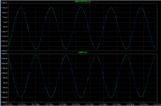
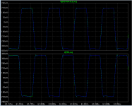
I ran simulations with R99=0.1 ohm and R99=1 Megohm, for sinusoidal primary current (resistor load) and for non-sinusoidal primary current (trafo secondary drives fullwave bridge rectifier with 10,000uF filter cap and heavy DC load). Hover mouse over image to read descriptive filename.Yes, the (DC) voltage distribution across each cap changes. The two series caps no longer make a 'traditional' bi-polar cap anymore. The junction of the two caps is now at a defined level whereas before it is not.
Upper pane is the voltage across C1 (measured +terminal to -terminal).
Lower pane is the voltage across C2 (measured + to -)
When I look at these pictures, it appears to me that the capacitor voltages are the same whether R99 is a million ohms (green trace) or a tenth of one ohm (blue trace). That's why the current flowing in R99 is femtoamperes: it is connected between two nodes that are nanovolts apart.
And I am merely applying one of the ancient and beloved tricks we all learned in EE201 when solving resistor hypercube homework problems:
If two circuit nodes are at precisely the same voltage, nothing changes when you short them together.
Installing R99 = 1Kohm does provide one minor benefit: it flummoxes and infuriates people unaccustomed to cutset analysis (tutorial) and/or circuit simulation.
_
Attachments
When I look at these pictures, it appears to me that the capacitor voltages are the same whether R99 is a million ohms (green trace) or a tenth of one ohm (blue trace). That's why the current flowing in R99 is femtoamperes: it is connected between two nodes that are nanovolts apart.
They will be nano volts apart because all the like for like components in the simulation are identical. Make one cap 10,700uF and the other 9400uF for example, and also change the ESR by a good percentage between the two and things might be a little different. Same goes for the diode volt drops, they are identical.
Of course I've tried those things and more, but the results haven't changed my mind; I still prefer R99=1K.... change the ESR by a good percentage between the two and things might be a little different. Same goes for the diode volt drops, they are identical.
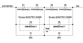
In fact I like the six-diode version even better (see below).
D1, D2, D4, D5 are standard high current silicon diodes, perhaps from a pair of integrated bridge rectifiers if you wish. D3 and D6 are high current (25A) Schottky diodes.
The whole shebang conducts DC current when the end-to-end DC voltage exceeds ((2 silicion diode drops) + (1 Schottky diode drop)) which is larger than the Rod Elliott four diode design shown in post #151. So it will block slightly more DC voltage than the 4 diode version.
Better still, this version connects a Schottky diode across each of the polarized capacitors, preventing the capacitor reverse bias from exceeding the very low (~ 0.3V) forward voltage drop of the big Schottky. So the capacitors are better protected against reverse bias. And the Schottkys themselves never see more than 2.2V reverse bias, so they can be low voltage devices like the 45V parts shown.
This circuit is more expensive than the the four diode version, of course. About (1/10th) of the price of a vacuum tube, more expensive.
_
Attachments
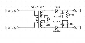
Just for fun, a useful circuit. The way to test it is to reverse the AC plug and see if the output voltage swings the other way to the same value. You might have to adjust the RC values depending on your meter and transformer.
To calibrate it use a two diodes in series with one anti-parallel. The whole thing in series with the AC line.
Mark you can use any diode of your choice. 🙂
To calibrate it use a two diodes in series with one anti-parallel. The whole thing in series with the AC line.
Mark you can use any diode of your choice. 🙂
Attachments
In fact I like the six-diode version even better......
At a quick glance and I quite like the look of that. Defining the maximum reverse bias voltage the caps can see seems to me a good thing.
A guarded yes to that one 🙂
Now place a shorting bar across D1 and another shorting bar across D5. Hmmm.At a quick glance and I quite like the look of that.
- Home
- Amplifiers
- Power Supplies
- DC blockers and mains filters