мои эксперименты с увеличением тока покоя положительно повлияли на звук. В этом выходном каскаде ток покоя задается не только базовыми резисторам 27 ом, но и соотношением размеров кристаллов выходных и пред выходных транзисторов, а также зависит от их коэффициента усиления. Так как параметры транзисторов могут отличатся в зависимости от партии, резисторы 27 ом могут быть пересчитаны, для обеспечения более высокого тока покоя, но оставляя транзисторы в зоне безопасной работы. Таким образом искажения падают еще больше и это заметно при прослушивании в моем случае.
I'm preparing an "Open Air Edition" with the 2 "leftover" board replaced by the new Cu Edition ones.
It will be close to the original project, no NSCB stage added, the only variations will be:
- the Baxandall couple;
- the 24 KOhm in place of the 2 x 12 KOhm;
- the remotion of the trimmer.
It will be assembled on a cutting board, recycling a lot of components coming from a Yamaha old audio/video center (a wonderful 400VA transformer, heat sink, big value capacitors...) bought used for $20. So it should be not too difficult to try different values of components in order to adjust the idle current.
Today I received the 7pF silver mica capacitors so I have everything needed but the soft start and speaker protection that are on their way from China. So I'm working on this Open Air Edition but can't say when I'll finish, I'm always late.
So do I but I still does not think it's a very good amp.
Could you expand your thought?
great, the process is gradually going on, I also tried both ceramics in the correction, and mica, with mica it sounds a little more transparent.Today I received the 7pF silver mica capacitors so I have everything needed but the soft start and speaker protection that are on their way from China. So I'm working on this Open Air Edition but can't say when I'll finish, I'm always late.
can someone please help me adjust the bias on this board?
HB-108 HIFI Power Amplifier Board Base on DARTZEEL circuit | eBay
I am sorry to post randomly here, but I have skipped through this thread but did not find the procedure and seller I bought this board from is no longer registered on ebay.
Thank you in advance for your help.
HB-108 HIFI Power Amplifier Board Base on DARTZEEL circuit | eBay
I am sorry to post randomly here, but I have skipped through this thread but did not find the procedure and seller I bought this board from is no longer registered on ebay.
Thank you in advance for your help.
Your board has 3 pairs of transistors in the output stage, the original project has only one, no emitter resistor and this should remain. Two pairs, three and more pairs, cannot be better than one pair because the topology limits the driving current to the one delivered by the two CCS, theoretical maximum 117.8mA. You can have as many pairs as you want, the driving current will remain 117.8mA.
I would eliminate the two more pairs and the emitter resistors by shorting them.
There is no trimmer to set the idle bias, it is determined by the 27Ohm resistors you see in the bases of output pair(s).
Some say it is more than 200mA, some say it is around 300mA. I wouldn't care too much about the bias provided it is within 200/300mA, I wouldn't change the 27Ohm resistor with different value ones, if you go a couple of months in the past you should find some posts by Analog_SA documenting the value of those resistors, showing that the best choice is 27Ohm.
Looking at the picture I see all pairs are driven by 27Ohm each. So the idle bias seems to be too high, if you decide to leave in place all the 3 pairs, multiply the 27Ohm by 3, 51Ohm, and drop the value of emitters resistors to 0.1Ohm 3W.
This is only a recommendation "on the chart", I didn't and won't try any of this.
great, the process is gradually going on, I also tried both ceramics in the correction, and mica, with mica it sounds a little more transparent.
I'm missing some screws that are on their way, incredible, I'm stuck because of screws!!!
Your board has 3 pairs of transistors in the output stage, the original project has only one, no emitter resistor and this should remain. Two pairs, three and more pairs, cannot be better than one pair because the topology limits the driving current to the one delivered by the two CCS, theoretical maximum 117.8mA. You can have as many pairs as you want, the driving current will remain 117.8mA.
I would eliminate the two more pairs and the emitter resistors by shorting them.
There is no trimmer to set the idle bias, it is determined by the 27Ohm resistors you see in the bases of output pair(s).
Some say it is more than 200mA, some say it is around 300mA. I wouldn't care too much about the bias provided it is within 200/300mA, I wouldn't change the 27Ohm resistor with different value ones, if you go a couple of months in the past you should find some posts by Analog_SA documenting the value of those resistors, showing that the best choice is 27Ohm.
Looking at the picture I see all pairs are driven by 27Ohm each. So the idle bias seems to be too high, if you decide to leave in place all the 3 pairs, multiply the 27Ohm by 3, 51Ohm, and drop the value of emitters resistors to 0.1Ohm 3W.
This is only a recommendation "on the chart", I didn't and won't try any of this.
Thank you so much for your detailed reply, I appreciate it.
Best Wishes
if you decide to leave in place all the 3 pairs, multiply the 27Ohm by 3, 51Ohm,
I have to correct myself, 27 x 3 is not 51 but 81. You can round it to 82Ohm
I too was in doubt about that capacitor because my speakers are Acoustat 1+1 that generate a lot of disturbance. I have to treat almost all amplifiers I connected to those speakers but, with this one, 7pF was fine. What I reversed as a mod was the 24KOhm resistor in place of the original 2x12KOhm ones: the rejection to the supply disturbance is worse, better to use the 2x12KOhm.
The delay time (signal transmission speed) depends on the correction capacitor, the lower it is the better for the voltage amplifier, at 7pf on signal square wave there is a small break, but it is not critical and does not affect the stability in General. I don't see much point in increasing the nominal value to 10pf.I am gonna use 10p instead of 7p for a slight earlier rolloff to prevent oscillations
Last edited:
Are you going to revert to the original configuration- 12k to ground?
First of all, I have to say that the setup I used to power up the circuit is a test one, very far from the ideal one: the power supply has only 4x1mF capacitors and long cables to deliver the power. In this condition, I have some hum that increases if I substitute the 2x12KOhm to gnd with one 24KOhm emitter to emitter. I cannot say so in the real thing (the closed WHA-217) because it seems to me to be silent, but there is no doubt that the rejection to the disturbance present in the power lines is worse. So, in one word, to answer your question, YES.
It is supposed to increase linearity and relieve the load applied to the preceding stage, without moving idle working points. I thought about this mod myself as I saw the schematic but my first attempts went bad because of fake transistors and, at that time, I renounced. Some time after, 3SSS posted this mod, so this was a confirmation for me and I did it. As I said in my last post, the mod worsens the rejection to the disturbance on power lines, but, with it, the offset, without a servo, is about 1mV and seems to be stable. I removed the mod in the Open Air Edition: the rejection to disturbance is better but the offset, without a servo, is around 1.2V.
I have to try it better. Now I must take a pause for Christmas time, I have a lot to do but, after the first week of the new year, I will continue my work on the Open Air Edition and will see.
In the meanwhile, we would appreciate a comment by 3SSS about this topic. 3SSS, Will you?
I have to try it better. Now I must take a pause for Christmas time, I have a lot to do but, after the first week of the new year, I will continue my work on the Open Air Edition and will see.
In the meanwhile, we would appreciate a comment by 3SSS about this topic. 3SSS, Will you?
Could you expand your thought?
Very undynamic kind of boring to calm and to nice. Resolution maybe ok.
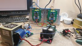
The speaker protection and the soft start boards arrived today. So I had everything to start the assembly on the bench. Here is in the picture, it works good, no hum, only one transformer, about 60mF total capacitors. It runs hot.
I could not understand well the quality of the sound, it was connected to the speakers in the lab, low-end ones. Seems to lack in dynamic and deep bass, not because of the power supply, which is strong enough for the tests I've done. The detail seems to be good, the sound a little hard. Very different from my WHA-217 that is very exuberant in dynamics and never harsh in sound. Will see, during the second week of the new year, I will assemble it on a cutting board and try it with Acoustat speakers.
I could not understand well the quality of the sound, it was connected to the speakers in the lab, low-end ones. Seems to lack in dynamic and deep bass, not because of the power supply, which is strong enough for the tests I've done. The detail seems to be good, the sound a little hard. Very different from my WHA-217 that is very exuberant in dynamics and never harsh in sound. Will see, during the second week of the new year, I will assemble it on a cutting board and try it with Acoustat speakers.
Attachments
- Home
- Amplifiers
- Solid State
- Dartzeel amp schematic - build this?