The problem with simulations is that you get a flood of numbers and lose insight. I know what I'm talking about: I did mathematical modeling in the era of IBM1130. Often it pays of to investigate the problem by using common sense and basics of physics. Now, use your numbers and verify my results which I have obtained easily by simple calculus and are more accurate i.e. can be validated with measurements.
Regards🙂
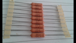
Unfortunately or fortunately, this is not my modeling (I am a practitioner), I posted the photo for possible help in numbers.🙂😉
Thanks
Now, we may conclude: all resistors 1/4W except R19 and R20, 600mW, perhaps 1/2W.
Cheers
Now, we may conclude: all resistors 1/4W except R19 and R20, 600mW, perhaps 1/2W.
Cheers
Hello everyone and thanks for your participation, I closed the issue with small resistors. In order not to suffer, I ordered all the small Takman 0.5W. The reserve (in terms of power) does not hold a pocket (Russian proverb).😉🙄
According to my measurements and calculations just R19 and R20 require higher power rating: 600mW.
My reasoning is as follows: voltage drop across these resistors is about 4.5V. This indicates that current is 115.4mA, i.e. P=519mW -
Am I correct?
No. R17 and R18 also have higher steady state dissipation.
But once signal is applied and amplified you have to consider AC dissipation as well. Resistors affected are the NFB 7.5k as the full output is developed across 7.5k + 360R and the resistors at the output transistors bases as the max output current divided by beta flows through the bases.
Hello everyone and thanks for your participation, I closed the issue with small resistors. In order not to suffer, I ordered all the small Takman 0.5W. The reserve (in terms of power) does not hold a pocket (Russian proverb).😉🙄
That's a pity because I think PRP or even Dale would be a better choice for this design. Not that I don't like Takman.
At one of the Russian technical forums, a comparison was made between radio engineers with great audio experience. Takman rey showed their best side, PRP is in second place, dale is even worse. But personally I think they are all good. It's a matter of taste. Then I will unsubscribe when I collect and listen.😉

Well, audiophiles are like enologists. They both rely on their own predudices. Tongue tastes what it wants, ears hear what they want. And yet, both renounce measurable facts because facts are usually in conflict with their opinions/prejudices.
Echo chamber effect is to blame. Give them vine/equipment in a bottle/box without a label and ask them to distinguish vine from vine and resistor from resistor. Enologists have better chance to guess, I think.
I will persist with Vishay.
Echo chamber effect is to blame. Give them vine/equipment in a bottle/box without a label and ask them to distinguish vine from vine and resistor from resistor. Enologists have better chance to guess, I think.
I will persist with Vishay.
@Erlend
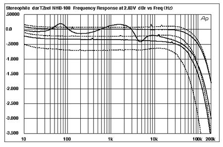
I have a good news for you: look at the image below from review by John Atkinson. His measurements are consistent with my measurements of the clone NHB-108. Note that he hasn't even bothered measuring below 10Hz.
This indicates that we have built pretty much fine amplifiers.
I have a good news for you: look at the image below from review by John Atkinson. His measurements are consistent with my measurements of the clone NHB-108. Note that he hasn't even bothered measuring below 10Hz.
This indicates that we have built pretty much fine amplifiers.
@analog_sa
Thanks for the answer.
I will further investigate this mater in more detail as my goal is not to build a cheap clone but to learn electronics. You will see my progress in six months or even sooner. I have always been an anorak. 😉
Thanks for the answer.
I will further investigate this mater in more detail as my goal is not to build a cheap clone but to learn electronics. You will see my progress in six months or even sooner. I have always been an anorak. 😉
I have 2 clones of KRELL KSA 5, the first on CCF 55, the second on RN 55, play equally well, but both are bright, I use it as a headphone amplifier and a preliminary to Dartzeel. So I decided to try something new. Here on the forum is my friend from the USA, which has 2 versions, one on Vishey, the second on PRP. Maybe he will write how they sound. I will not convince anyone, we listen with ears.😉😀
I'm sure you will build yet another fine amplifier. 🙂I have 2 clones of KRELL KSA 5...
Last edited:
At one of the Russian technical forums, a comparison was made between radio engineers with great audio experience. Takman rey showed their best side, PRP is in second place, dale is even worse. But personally I think they are all good. It's a matter of taste. Then I will unsubscribe when I collect and listen.😉
Agree with those Russians but it all depends on the construction. The Dartzeel needs something brighter then Takman.
On resistors mrs 25 dartzeel separately sounds like a new vinyl record. The preamplifier on Dale, in my opinion, adds brightness, it seems to be beautiful, but for me a lot and it sounds like a CD. And I want to remember my youth, the lamp and the coil.🙂
Have PS Audio Direct Stream gear and maybe a little bit to the dark side. But use silver XLR cables. And silver /Gold /Oil Mundorf across my Duelund cast in speakers.
cpf 3 4.7k is enoughPerhaps,
There are two metal film resistors we can use directly:
Vishay CCF024K75FKR36 Metal Film Resistor - Through Hole 2watt 4.75Kohms 1%
Vishay CCF026K80JKR36 Metal Film Resistor - Through Hole 2watts 6.8Kohms 5%
As suggested elsewhere in this conversation, the remaining 39R/5W could be attained with two parallel
CPF282R000FKE14 Metal Film Resistor - Through Hole 2watts 82ohms 1% 100ppm
But, first, I will measure real power demand with +-42V rails.
Perhaps, analog_sa is right: why would we follow exaggerated wattage ratings. And why should we build a 100W to listen to it home at just 1 to 2 percents of its capabilities. Perhaps the Chinese have exaggerated these +-55V rails.
Lets measure.
Have a pleasant nigh. I think I should go to bed now.
Bye
Attachments
Thanks Sensation45. Your suggestion is welcome.🙂cpf 3 4.7k is enough
Meanwhile, I have made some calculations and found out that there is no need for exaggerated desin margins which involve selection of wirewound resistors.
Now I have decided to use 1/4W resistors everywhere except 600mW for R17, R18, R19, R20, R25 and R26.
Measurements indicate that widely addopted excessive power ratings are unnecessary. Just take a pencil and a sheet of paper and calculate from the values in the schematics. It appears that the designer/cloner had some plans in his mind and has built in design margins but later has abandoned his plans and forgot to go back to lower rated resistors.
I will inform you if I get some smoke from my PCB with much smaller resistors.😱
Not a word on how those were matched. The important thing is "not Made in CHINA cheap fakes". Utterly hilarious.
- Home
- Amplifiers
- Solid State
- Dartzeel amp schematic - build this?