Bass attack. That's a new term to me.😀 and I'll forget it as soon as I can. (Please understand, i'm not disrespectful towards you, just like to smile.)
There is a lot of snake oil in the field of audiophile talk. I always try to stay faraway from that slippery slope.
The lowest tone I have created ever was F1 (44Hz) on Kaiserbass. I used to play it as a young guy and did it just fine.
Now, let me tell you more on this subject, from the view of a musician.
Distance from 5 Hz to 20 Hz seems at the first glance insignifficant, but it contains two octaves, indeed of non existent, phantom tones, yet two octaves.
Let's take, for example the most common tone C3 - it has frequency of 130.81Hz and a tone one octave above it is C4 that has 261.63 Hz. Octaves differ by the multiple of two.
Similarly 5Hz and 20Hz are two octaves appart and that's a lot.
Frequency of octaves double. Hence frequencies and sound (decibels) are best presented in logarithmic scale and should be understood this way.
I will survive just fine with an amplifier which has 5Hz cutof frequency, and more important it almost never rolls of in higher frequencies, even at 200KHz.
PS:
Furthermore: 0.5Hz is needed by the "audiophiles" for the "bass attack". Show me a speaker capable reproducing that?
Last edited:

 Impressive indeed!
Erlend Sæterdal You changed the value of R101 and R102 to 51kOhm, what is the resistance of the trimmer P1, as your version of dartzeel?
Hello community, Berlusconi asked a question but he must be busy, decided to ask everyone. A friend sent Takman REY 0.25 watts, I want to use it on the new board version 1. Put them (according to the scheme) everything except R11 / 12, R21 / 22, R23 / 24 (0.5 watts will be), well, leave powerful 2 watts and 5 watts respectively. What do you think is possible? The power supply of the amplifier is 46 volts constant. I also thought about increasing the quiescent current of the output stage by reducing R23 / 24 to 20 ohms, now the radiators are warm, they recommend on the Russian forum.😕
Erlend Sæ Thank you, how about the resistor question, is it possible to set 0.25 or put everything at 0.5 watts?🙂
Hello my friends,
You have just opened important questions: values of several resistors. Until now I had no choice except to stick with values on the silkscreen and a BOM I have found on internet. According to the BOM:
R25 and R26 are 4K7 2W (VISHAY BC PR02 5% 4mm*12mm),
R17 & R18 are 6K8 2W (VISHAY BC PR02 5% 4mm*12mm),
R19 & R20 are 39R 5W BC Philips
I would like very much to replace these with smaller power rating to be able to use metal film instead of wire wound. However, I am still unsure if and to which extent I can reduce power rating.
Perhaps it would be the best to force the amplifier with high power and measure voltage across these resistors to calculate power rating required for these resistors. Hopefully, I will be able to use metal film resistors consistently.
Please, note that I do not want or intend to change anything, I am not an expert and do not want to pretend to be. I'm just an ordinary DIYer. I am confident that the PCB is 1:1 clone. At least, the clone has frqquency response equal to the published parameters of the original amplifier.
However, I am not sure that the data from the BOM is accurate. This is the reason I will investigate this dilemma.
There are several hard working days behind me and I'm finally back home. Tomorrow I have one meeting and I am a free man until the end of the next week, but I will work on cloning Dartzeel.
Let's keep in touch. 🙂
I think, we already have answers to all questions about the power rating of these larger resistors....
I prefer using MF resistors everywhere. For high power Caddock thick film MP series, for less demanding high power applications non inductive Mills. Metal oxide is generally not to my taste.
In my 108 clones i don't use any big resistors. The 4.7k dissipates 355mW and the 6.8k - 380mW. In both positions i think i have 1W metal films.
The 6,8k resistor is probably not very audible and a MO may be just fine. The 4.7k otoh may be extremely audible.
Sorry, forgot you were asking for a choice between WW and MO.
In this particular instance there is no issue with the 4.7k being inductive. On the contrary, the more inductance, the merrier 🙂 The 6.8k should be non inductive so a MO is fine.
Unless you forget about the excessive wattage ratings and go for 1W MF.
Thanks analog_sa. 🙂
Perhaps,
There are two metal film resistors we can use directly:
Vishay CCF024K75FKR36 Metal Film Resistor - Through Hole 2watt 4.75Kohms 1%
Vishay CCF026K80JKR36 Metal Film Resistor - Through Hole 2watts 6.8Kohms 5%
As suggested elsewhere in this conversation, the remaining 39R/5W could be attained with two parallel
CPF282R000FKE14 Metal Film Resistor - Through Hole 2watts 82ohms 1% 100ppm
But, first, I will measure real power demand with +-42V rails.
Perhaps, analog_sa is right: why would we follow exaggerated wattage ratings. And why should we build a 100W to listen to it home at just 1 to 2 percents of its capabilities. Perhaps the Chinese have exaggerated these +-55V rails.
Lets measure.
Have a pleasant nigh. I think I should go to bed now.
Bye
 ...
...
Ah, this is so simple even for me, an amatheur. Just by looking at the schematics this is a simple matter of ordinary calculus. Of course: all you need are Kirchhoffs and Ohms laws to solve this problem. That simple is that.
Hint: sum of potentials in a closed loop equals to zero.
This is a good excersise.
Solutions, please. I know the answer.😎
Here are the answers for +-42VDC rails:
R19 & R20: P<0.666W
R17 / R18: P<0,201W
R25 / R26: P<0.154 W
Note that:
the voltage drop across R19 & R20 must be lower than 5.1V
the voltage drop acrossR17 & R18 is lower than V(rail)-5.1V (note that this is substraction: V(rail) minus 5.1V=42-5.1V=36.9V)
the voltage drop acrossR25 & R26 is lower than V(rail)-15.1V (note that this is substraction: V(rail) minus 15V=42-5.1V=27V)
You can use these formulas to calculate the values for other rails.
This means that all these large wire wound resistors are unnecessary complication.
Calculation results can be verified by simple measurements with multi-meter across the resistors. In all these resistors there is just DC.
Intability of current through the resistors R19 and R20 can cause problems. To prevent any fluctuations at this point it is necessary to use 100u electrolytic and 100p film capacitors in parallel and these should be connected on one side to the power supply, the other side should be connected to the PCB, with the shortest possible wiring. This simply terminates any buzz, hiss, hum etc. For more information read the article at the TNT site.
Last edited:
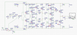
A five year old could not have put more voltage and current labels 😀
Otoh, the models for the outputs are not very realistic, even at dc.
All information for you is only for informational purposes, I am waiting for advice on the main small resistors, it's time to order for 0.5 watts.😉😀
First, I'm glad to see analog_sa back again among us. I feel more confident now as we all need his advice.
If I may one question analog_sa:
According to my measurements and calculations just R19 and R20 require higher power rating: 600mW.
My reasoning is as follows: voltage drop across these resistors is about 4.5V. This indicates that current is 115.4mA, i.e. P=519mW -
Am I correct?
If I may one question analog_sa:
According to my measurements and calculations just R19 and R20 require higher power rating: 600mW.
My reasoning is as follows: voltage drop across these resistors is about 4.5V. This indicates that current is 115.4mA, i.e. P=519mW -
Am I correct?
Last edited:
analog_sa Thank you, I trust your opinion. Therefore, the last (I think) question is about small resistors. Pay attention to the power and sizes of the resistors that I give here and explain, if you can, the ratio of size and power. PR 9372 -0.25W, length 7.5mm, diameter 2.75mm; Takman rey -0.25 W, length 6.3mm, diameter 2.6mm; MRS 25- 0.6W, length 6.5mm, diameter 2.5mm. The latter was put in the original. You said that 0.25W can be supplied, but this applies to these elements, or if the size is smaller, is it better to increase it to 0.5W? Please do not kick too much.🙁
- Home
- Amplifiers
- Solid State
- Dartzeel amp schematic - build this?