I have been looking at such protection for a long time, the opinion of experts is also interesting.
It will work fine as a dc protection for Dartz. It's presence is too audible in my system but it may be completely transparent to others 🙂
Over the last week I have been experimenting with adding an additional pair of transistors to one of my 108 clones.
This particular amp feeds the bass speakers in one of my systems, so that is where I did most of the listening.
The transistors were only beta matched at around 1A. Two types of emitter resisors were used: Dale 5W inductive ww 0.1ohm and Caddock thivk film MP930 0.25ohm. Despite the lower damping factor with the Caddocks the sound was much better, even the bass.
As a whole the experiment was not successful. These particular speakers did not benefit from the added current ability and the added transistors/resistors destroyed all midrange magic the amp had previously. Surprisingly, even though feeding only a bass speaker (350Hz) the effects of the emitter resistors was audible even in the treble.
I also tried the amp as full range with some pretty demanding speakers that dip below 3 ohms. With a single transistor pair it was almost unusable with those speakers whereas with 2 pairs it became quite enjoyable. Some midrange roughness that paralleling brought was again evident but for some reason not so annoying.
This saves me the effort to design new boards as the parallel 108 is clearly not for me.
It could but some still remark that they can hear a Switched On Mosfet into the signal path (same as a speaker relay, but of much lower Ron). The main purpose of the SCR protection and current sensing transformer of the original was to have nothing in the output signal path that can affect the sound.
The Original protection was: Overtemp switch (can be seen on the side of the protection relay), DC level protection (possible location of the DC sensing circuit is on the rear input pcb), over current with current sensing transformer. The amp also sense the output level to turn on and indicate clipping output levels (possibly the same DC detection circuit with different comparator levels).
The documentation also states the in the amp OFF state, 2V remains on the main supply power supply caps. Possibly the original circuit is always sending the transfo rectified voltage to the protection pcb, that as +/-15V TO220 regulators mounted on heatsink, and from there a small 2V is sent to the main power capacitors, keeping them polarized. A high current relay, possibly under the transformer may connect the main power and filtering caps at power-on. A simple diode could when reverse bias by the main +55V supply voltage, turn off the standby 2V on the caps.
The protection pcb is probably always on, monitoring evrything, and starting the amp...
Last edited:
over current with current sensing transformer.
Pardon me S, but wasn't that a Hall element? Not that it makes a whole lot of difference.
Same here. To many reports of a "it is noticeable" and not in a positive way. Using MosFets on power rails is reported as much less noticeable. But still, I want absolutely bullet proof speaker protection and only clamp(crowbar) style can achieve that when supply rails running over 50 Volts in particular. I had once cooked RT314 at 32 Volts rails. It is a way cheaper and easier to replace output transistors and fuses than trying to find expensive/rare/out-of-production/vintage woofers and often not even one pairIt could but some still remark that they can hear a Switched On Mosfet
Last edited:
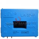
Here the sensor I believe, LEM LA55-P, indeed Hall effect, 50A, but still current sensor...
Attachments
Last edited:

Lay out the scheme with crowbar.Same here. To many reports of a "it is noticeable" and not in a positive way. Using MosFets on power rails is reported as much less noticeable. But still, I want absolutely bullet proof speaker protection and only clamp(crowbar) style can achieve that when supply rails running over 50 Volts in particular. I had once cooked RT314 at 32 Volts rails. It is a way cheaper and easier to replace output transistors and fuses than trying to find expensive/rare/out-of-production/vintage woofers and often not even one pair
Returning to protection, after all, a mosfet can also be included in the power of the amplifier or use the circuit on a triac?
Again, it depends on what is audible to you. I have tried the mosfet switches (9mohm) in the powerlines and found those to be too clearly audible.
The triac is the best solution with regards to audibility but it's mode of operation is inherently violent 🙂
From Stereophile:
"Unfortunately, when I approached clipping with this signal, a click emanated from the NHB-108, which I assume was the crowbar protection circuit cutting in. Before I could reach over and tug the AC cord loose, there was a loud bang from the left-channel output devices and my test lab filled with blue smoke. Once my ears had stopped ringing, it turned out that, when I'd last replaced the fuses, I had inadvertently used a slo-blo type for the left channel."
@Paroxod4
Further to your crowbar circuit. It is very simple as it only provides DC protection @0.8v. That 10A fuse is not something i would enjoy having in series with the speakers. The crowbar in the original 108 is supposed to blow up a fuse in the primary of the PS transformer.
Further to your crowbar circuit. It is very simple as it only provides DC protection @0.8v. That 10A fuse is not something i would enjoy having in series with the speakers. The crowbar in the original 108 is supposed to blow up a fuse in the primary of the PS transformer.
Yes, I also read it.Again, it depends on what is audible to you. I have tried the mosfet switches (9mohm) in the powerlines and found those to be too clearly audible.
The triac is the best solution with regards to audibility but it's mode of operation is inherently violent 🙂
From Stereophile:
"Unfortunately, when I approached clipping with this signal, a click emanated from the NHB-108, which I assume was the crowbar protection circuit cutting in. Before I could reach over and tug the AC cord loose, there was a loud bang from the left-channel output devices and my test lab filled with blue smoke. Once my ears had stopped ringing, it turned out that, when I'd last replaced the fuses, I had inadvertently used a slo-blo type for the left channel."
The Supply Mosfet switches could be before the main capacitor banks, not after. In this case the crowbar circuit is need to rapidly discharge the caps to protect the amp and the output. There is probably some kind of power supply switching into the original because the user manual mentionned 2V standby voltage on the caps, and that the power switch activates a starup cycle. So it is relay or Mosfet, and the amp sounds good apparently...
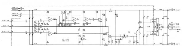
As for the Crowbar and protection, as pointed by sa_analog, the Revox A740 SM shows probably something similar to what is used into the amp, here the schematic.
On the left, DC level detection, in the middle level comparators, and 'OR' diodes for the multiples amp fault (overtemp, over DC volt, (the overcurrent is managed by a classic current limiter circuit into the amp using the emiter resistor sensing)) and the crowbar SCR that short out the main power supply cap bank.
Into the original the current sensor output, after conditionning can be added with an extra 'OR' diode. Also the Overtemp switched fixed on the heatsink seems to go under the power transformer pcb, not the protection pcb, indicating that the overtemp shutdown the amp power, but doesn't activate the crowbar (just a theory...).
The original protection pcb has trimmer probably to set the detection threshold of the different led indications, such as this sequence:
Start monitoring Current and output Voltage:
-If no input signal (<10mW into 8ohms at output), for 45sec, then turn ON front led, LOW intensity
-Signal presence detected (>10mW into 8ohms at output), then turn ON led at MEDIUM intensity
-Amp reach its maximum power at output. Flash led for 1sec at HIGH intensity, then get back to MEDIUM, wait at least 1 sec before flashing again if power still reach maximum
-Continue to check for fault and to monitor Output level, activate leds as needed...
The led activation, delay, intensity change, etc can be manage again with a similar circuit as the one presented into Headwize EL84 Headphone amp (by Helmut Ahammer) I studied, here the leds activation circuit.
What is just missing really would be the current sensor conditionning circuit...
Attachments

The Supply Mosfet switches could be before the main capacitor banks, not after. In this case the crowbar circuit is need to rapidly discharge the caps to protect the amp and the output. There is probably some kind of power supply switching into the original because the user manual mentionned 2V standby voltage on the caps, and that the power switch activates a starup cycle. So it is relay or Mosfet
This is an interesting hypothesis. But what makes you think the mosfet switching is not at the transformer primary circuit?
Because the amp stays with 2V on the psu caps when in the Off states ant that the protection/monitoring pcb has to stay enrgized to start the amp (like a standby mode), and it doesn't seem that there is extra standby power supply transformer into the enclosure. Maybe under the main transfo, but it has to be quite small, but that's a possibility as well...
SB
SB

When I have time and have mine ready with pcb. For experiments I used modified opto protection developed by lynx. But any dc detection circuit which triggers only when dc present, will do, like any of clamp circuits from stage ampsLay out the scheme with crowbar.
What fuse in series with the speakers? There is no such thing and I never seen anyone doing it. Crowbar clumps the output and blows fuses in supply rails, that's the whole point. AFAIK crowbar in 108 does the same. The reason for it: there is no point to blow fuse in primary when your rails have 100mF of capacitance charged to 50-55 Volts. Where all that energy should dissipate when your output is shorted? Also it is quite the challenge to blow the fuse in primary during standard operation, by shorting amplifier output when your secondary rails buffed by 100mF caps. I'm not saying it is not possible but doing this is not as simple as it seams.That 10A fuse is not something i would enjoy having in series with the speakers. The crowbar in the original 108 is supposed to blow up a fuse in the primary of the PS transformer.
Sorry S, i fail to understand the importance of those 2v in the grand scheme 🙂
Must have missed noticing this in the manual. Is it to keep the big caps always slightly charged?
Not sure i like the idea of there not being an auxiliary transformer somewhere, even a tiny 3VA unit. Shorting the output will lead to a collapse in the magnetic flux that will affect all other secondaries. Will the SCR remain triggered for long enough for the fuses to blow under such conditions? Maybe it can be made to work but it doesn't seem like a very clean solution.
There is also plenty of space underneath the toroidals and even the corner of a pcb can be seen there. Having the soft power on switch at the primary will also be much less audible.
Last edited:
What fuse in series with the speakers?
I was addressing the circuit in #909. Does it not have a fuse?
- Home
- Amplifiers
- Solid State
- Dartzeel amp schematic - build this?