Why should it be it is fully determined by the input stageHas anyone noticed a difference in measuring the offset voltage at the output of an amplifier with one pair of transistors and with two pairs per channel?
Is the amplifier with 2 pairs of transistors per channel more unstable in terms of varying the offset voltage?
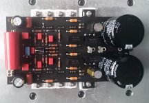
Have only one positive property - cheap. Not very good layout, maylar caps and almost certainly only 35um copper. This board and alike, including copy of original, were the reason for me to sick better designs ending up developing my own. But given that pcb including all the components is least expensive part of an amp you not risking much.I will also order a PCB with only one pair of transistors (they are not expensive anyway). Is this a good PCB?
300W-500W After Stage Amplifier Circuit PCB Board Amp base on darTZeel NHB-108B 699997083198 | eBay
Why should it be it is fully determined by the input stage
Of course. I even tried the output diamond with a valve input stage. As it was transformer coupled, meaning there was very low resistance between the diamond bases and ground, the offset was practically nil.
Did you notice my earlier speculation that model 2 uses the same type of transistors for both drivers and outputs? Do you think it is worth doing it like that?
I don't have opinion on this matter.Did you notice my earlier speculation that model 2 uses the same type of transistors for both drivers and outputs? Do you think it is worth doing it like that?
MJE 15032 and MJE 15033 output transistor? Can put it without any changes? Has anyone tried?
This would further reduce the cost of the amplifier and make it easier to pair the transistors.
How would it affect the sound of the amplifier?
This would further reduce the cost of the amplifier and make it easier to pair the transistors.
How would it affect the sound of the amplifier?
Last edited:
It will blow up, perhaps even from idling. If that doesn't change the sound I just don't know what does 🙂
How much it reduce the final cost 0.3% or 0.5%. Cost of power supply caps heatsinks and more less decent enclosure dwarfing the cost of parts you soldering on pcb. Over course of a year I had over two hundreds pairs of 32/33 to match from 4 different sources (digikey/mouser/newark/arrow). Ask me how many I managed to match within at least 10% ... zero, 20%.... few 30% and up her we starting to get somewhereThis would further reduce the cost of the amplifier and make it easier to pair the transistors.
Two extra transistors per board not going to make any difference whatsoever.
Last edited:
I was just thinking about cost of transistors, not the total cost of the amplifier.
If you bought 200 pieces of 22/33 you don't have to buy another 200 pieces of output 02/81 to pair them well
If you bought 200 pieces of 22/33 you don't have to buy another 200 pieces of output 02/81 to pair them well
As you were already answered the 22/33 are impossible to pair no matter how many you buy, they are just too different.
So why are transistors that can't be paired installed at all? I believe there are a lot of others that would fit the same and that can be paired without any problems
Well, let's say for 15030/15031, the replacement of D44H and D45H, but what to change 32/33 for?
But, of course not. When I've met my wife she was blonde and I had black hair, but we've matched splendidly. Some things simply go together even they "do not match". 😉Perhaps because it doesn't matter?
There is a tester DY294, how to choose transistors correctly and quickly? 15032/15033?
Last edited:
Matching those makes zero sense to me. What does make sense is getting equal current gain for both sides of the buffer, which is perfectly fulfilled with 2 matched pnp and 2 matched npn parts. Does anyone have a different theory?
Took a new batch of 20 pieces measured, with a base current of 1mA, beta at 32 on average 113, at 33-179. Better not selected. There are 30/31, respectively 122/136.
cost of transistors particularly 32/33 is negligible in total cost of an ampI was just thinking about cost of transistors, not the total cost of the amplifier.
32/33 at 100 pieces less that a dollar and you need 16 per set. 02/81 are $2.65 @ 10 to 100 and you need just 4 per set. and 02/81 pairs a bit betterIf you bought 200 pieces of 22/33 you don't have to buy another 200 pieces of output 02/81 to pair them well
Exactly 🙂 it is desirable but not requiredPerhaps because it doesn't matter?
This week-end I spent time on the dartzeel especially to understand why the offset was moving and why the offset of the two ways seemed to be linked.
This evening I am happy :RÉ to have found the cause:the two ways need there own power supply and I was making all test with only one.
At this moment offset 2mv/0mv at the power on 4 hours ago 4mv/20mv and quickly close to zero. No effect of adjustment of one on the other.
I have read exchange on speakers protection, I will put relay and listen may be I will hate as said analog_sa .
I understand the best way is the crowbar with the risk to destroy the power and the crowbar isn't it?
Have a nice day or night 🙂
Last edited:
@dougan
I's hard working week behind me and yet another in front of me, but I simply must remain on-topic here because things are developing well here.
Thanks for this good news: now we know which way to go:
1. Parts from reliable supplier
2. Copper cap on 5551/5401 transistors
3. Two separate trains of power supplies
4. Speaker protection board
5. Soft-start board for power supply.
However, I can see furter improvement: Another board suggested by Paroxod4 and built by "garrbage". I am shure this board is the way to go further towards even better sound. I'm not sure but as far as I can understand, this modifier board addresses important issue: inductance of wirewound resistors.
I hope our friend "garrbage" may provide us with more information about this board.
Attachments
Last edited:
but as far as I can understand, this modifier board addresses important issue: inductance of wirewound resistors.
Uh, what?
The board has one obvious advantage: it places the large electrolytics exactly where they are needed. Not sure whether it solves the only real issue of the "original" layout - the poor grounding, which does not separate the input grounds and instead uses the lazy ground plane approach.
Btw, not sure if this has been discussed in the thread, but the original 108 does not connect the speaker return to the ground terminal on board but instead to the capacitor bank. It makes a subtle but worthwhile improvement.
- Home
- Amplifiers
- Solid State
- Dartzeel amp schematic - build this?