Sorry for error :
I applied this on my phono preamp on 2sk170 and BF 245 with very good result and with much less hum and noise.
I applied this on my phono preamp on 2sk170 and BF 245 with very good result and with much less hum and noise.
My apologies I wasn't clearMy post contains two claims. Perhaps you should make it clear which of the two you disagree with 🙂
This one
At the same time there is a substantial improvement in other areas: bass, solidity, dynamics and technically the ability to drive low impedance loads.
Thanks, your contribution to this discussion is very valuable and is appreciated. "Garrbage" is incredibly valuable with his expert knowledge and more important as a very nice person prepared to help and guide us. I can see now here very collaborative and positive working atmosphere and results are already here:garrbage I welcome to this forum, friends, I fulfilled my promise and invited him to us.
Our friend dougan has made his boards controllable which is good guidance for all of us. This weekend I intend to desolder 2n... transistors and replace them with new in copper housing.
Cheers dear friends

Phono preamp sensitivity is 3mV, amplifier in question 20 time that. I don't see the point doing it. Even shielding large input caps doesn't seam to have any effect in normal conditions.I applied this on my phono preamp on 2sk170 and BF 245 with very good result and with much less hum and noise.
Yesterday I leaved the amplifier hot with offset Left ans Right channel close to +-16mv
This morning amplifier cold ( 20°C)immédiatly after power on L-107/R+140 degreasing 2 minutes later L-79:R+110 degreasing and stable when I come back 45 minutes later.🙂
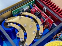
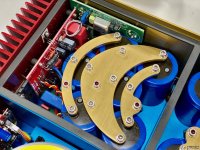
I could say the copper heatsink is a very relevant solution concerning the stabilisation of the offset Thank you very much Parodox4 for this
I tried this afternoon to achieve offset zero it is not so easy because the two channels offset seems to be linked you touch one the other move
Iwould like to know why if anybody know I thank you.
Nevertheless at this moment L-5/R+5mv 🙂
I know that fuse or relay isn't the dartzeel philisophy, are you using speakers protection ? Is the sound affected?
This morning amplifier cold ( 20°C)immédiatly after power on L-107/R+140 degreasing 2 minutes later L-79:R+110 degreasing and stable when I come back 45 minutes later.🙂
I could say the copper heatsink is a very relevant solution concerning the stabilisation of the offset Thank you very much Parodox4 for this
I tried this afternoon to achieve offset zero it is not so easy because the two channels offset seems to be linked you touch one the other move
Iwould like to know why if anybody know I thank you.
Nevertheless at this moment L-5/R+5mv 🙂
I know that fuse or relay isn't the dartzeel philisophy, are you using speakers protection ? Is the sound affected?
I use Chinese protection on the relay and the 1237 chip, to be honest I can’t catch better or worse.
Is the sound affected?
It depends upon how much you are bothered by the sound of relays. Some people don't notice them at all, i cannot stand them and would not use them. Ditto for mosfet relays, despite the milliohms 🙂
A friend uses short lengths of thin silver wires in lieu of fuses at the output of his Dartz clones. His speakers are about 100db/W/m so he is understandably cautious.
Hi there,
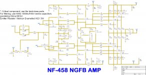
Finally, I decided to contribute what I have done, NF-458.
NF-458 stands for Non-Feedback 458.
Some Disclaimer:
1. I have no intention to imply or claim that this scheme has ANY relationship to DartZeel's any product, especially NHB-458.
2. It is my personal iteration of non-global feedback design, which may or may not be similar to NHB-458.
3. I have no intention to imply that NF-458 is identical to NHB-458, it is reader's own decision to consider whether NF-458 is or is not identical, or similar to NHB-458.
4. All information posted here is hosted just for discussion purposes and provided AS IS.
5. In no event shall the author, I, or any other 3rd party, be liable for any special, direct, indirect, or consequential damages or any damages caused by any form of this scheme.
Attachments
Last edited:
As I wrote, I have a Dartzeel amplifier from a quinstor. I haven’t done anything on the board yet, I turn it on, measure left 27mv, right 25mv. After 10 minutes left 16mv, right 14mv. I warm for half an hour - left 2mv, right also 2mv. It is unclear why some are so bad, I don’t praise the Chinese, but there are questions.:смущенный:
Speaker protection is a "must have" option. If rails running over +/- 40 Volts. Descent relays suited for high quality equipment (Shrack RT314 with contact material Ag Au clad) are running out of luck (pun intended).I know that fuse or relay isn't the dartzeel philosophy, are you using speakers protection ? Is the sound affected?
If you look in RT314 datasheet you'll notice that despite 16A AC rating, DC breaking capability is barely over 2 Amps at 40 Volts. For 4 Ohms rated speaker when Re usually around 3 Ohms it is almost 12 times rated current. To often when output stage blows relay contacts get welded together with obvious consequences to the woofer(s).
For amps with higher voltages it is even more critical. Finding device capable of safely disconnect 55 Volts of DC at 15-20 Amps and not affecting sound quality it is far from being a trivial task.
Price wise Dartzeel is far from being cheap amp and it is safe to assume that speakers connecting to it are in the similar price range. Cost of replacing couple of transistors is far less greater that replacing scorched expensive/out-of-prod/vintage woofer(s).
Hence - Dartzeel uses clamp (crowbar) approach it blows fuses between filter caps and amp supply rails.
There very few options with relays (only with Ag Au clad contacts):
a. use two contact groups/relays in serial
b. connect NC contact to ground (not actually iron clad option but there are reports that it helps to reduce number of cases with welded relay contacts)
Relay with higher DC rating like 8A@50V DC would work but so far I fail to find Ag Au clad contact materials in such relays.
I just notice them but it is not bothering me, Ag Au clad contacts keeps irritation levels undetected 🙂 My concern is mostly safety. Particularly when you connect other people speakers to it.It depends upon how much you are bothered by the sound of relays. Some people don't notice them at all, i cannot stand them and would not use them. Ditto for mosfet relays, despite the milliohms 🙂
There are those among us who simply need a parallel output stage. In my case this need is is determined by a pair of difficult speakers in the bedroom that stubbornly refuse to play with the original clone.
The obvious source of inspiration is of course the Model 2, which has 2 pairs of output transistors. Sadly, there are only a couple of pics i can find, none of which taken with the thought of reverse engineering it 🙂
Here is what is known and what can be seen or speculated.
1. No more manual adjustment of the offset. The board at the back is the same only the offset jumper is not in place. A very large WIMA cap is at the input, giving the impression that the dismal pair MKS have been replaced with the slightly more tolerable MKP. The much bigger size is possible because of the space freed up by the removal of the offset correction.
2. L/R channel are now not identical but mirror images. Not so great for reversing as this makes only one side of the board being visible.
3. The board appears to have become wider as all the outputs are at the narrow end. The drivers have disappeared underneath and here is the first baffling bit: they appear to be no longer TO220 but rather TO264. This certainly makes sense as the correct way to build a diamond buffer is by using identical transistors everywhere. What is not seen are holes in the pcb to access the screws. While certainly possible to assemble the board without having access to the screws this appears a bit weird.
4. Emitter resistors. This one really baffles me. There are 4 x 5W resistors, but the position on the board is just wrong. Cannot see any good way to wire this up.
What about the value? The Chinese clones use 50mohms here which is good for the damping factor and not so good for equalising the currents. The Model 2 appears to use Dale CW5 resistors which start from 100mohms and this probably represents a more realistic value.
5. The base diodes, the ones that received a mention in the patent for Model 1 are also not to be seen. Perhaps the board now has smd components mounted on the bottom side. The supercap is certainly easy and appropriate to mount there, so maybe not all components are seen from the top.
Some of the above is speculation and likely wrong. Thoughts?
Attachments
Speaker protection is a "must have" option.
I agree with everything in your post apart from the opening sentence 🙂
There are a huge number of high end amps which do not use relays and often any protection apart from PS fuses. Yet, casualties appear to be low. After hearing what relays do to the sound i stopped building protection circuits and that was many, many years ago. Knock wood, no blown woofers so far 🙂
Ironically, the relays with contacts capable of withstanding the currents a protection system should handle are also the worst sounding. Mosfet relays are a bit better but still not very transparent. All imho of course as i am well aware the vast majority of diyers suffer from an acute form of DC paranoia 😎
My experience with MOSFET “relays” at the amp output is not good either. Many people swear they are totally transparent, however my ears tend to disagree...
That is only until the following standsI agree with everything in your post apart from the opening sentence 🙂
After that views changing radically.no blown woofers so far 🙂
DittoIronically, the relays with contacts capable of withstanding the currents a protection system should handle are also the worst sounding.
What I heard form the people who tried to use mosfets in signal path it is _quite_ audible (Thanks selfy). There is an option of using mosfets to cutoff supply rails. That works quite nicely but for higher supply voltages I prefer professional approach - crowbar 😉Agree her Mosfet relays are a bit better but still not very transparent. All imho of course as i am well aware the vast majority of diyers suffer from an acute form of DC paranoia 😎
There is another option of carefully selecting fast blowing fuses of appropriate value with very steep curve in supply rails, but price tag for those not attractive at all.
Last edited:
There is an option of using mosfets to cutoff supply rails.
Tried that out using the same mosfets I have in the 4320 rectifiers. Sadly, even that is disappointingly audible. The crowbar solution is probably the best as far as audibility goes. And it is tastefully violent 🙂
Has anyone noticed a difference in measuring the offset voltage at the output of an amplifier with one pair of transistors and with two pairs per channel?
Is the amplifier with 2 pairs of transistors per channel more unstable in terms of varying the offset voltage?
I will also order a PCB with only one pair of transistors (they are not expensive anyway). Is this a good PCB?
300W-500W After Stage Amplifier Circuit PCB Board Amp base on darTZeel NHB-108B 699997083198 | eBay
- Home
- Amplifiers
- Solid State
- Dartzeel amp schematic - build this?