for me I think mesure offset at the output without connecting charge and input and adjust with P1 is it ok?
Thanks for reply. For me this is logical but I've heard that NHB-108 should never be ON without load: speakers or adequate resistor. What really puzzles me is the purpose of that "DC" point, which is simple connection to the viper of the potentiometer. Furthermore, in the clone instructions they propose to first adjust potential at the "DC" point and then adjust potential at the output. This seems to me conflicting: there is just one potentiometer and it is impossible to set two values simultaneously. For me that is exclusive, either-or situation.for me I think mesure offset at the output without connecting charge and input and adjust with P1 is it ok?
On the other hand, there are different but comprehensive instructions in original darTZeel"Audiophile's Technical Manual". In chapter 12. entittled "Special Adjustments" in subsection "12.1. Output Voltage Drift".
I think I will stick with the original Instructions and trash that cryptic, fake Chinese instructions alltogether. No offence meant but these instructions seem to be absolutely inacurate and conflicting.
One more thing: if you intend to order bare PCB, it is new model, yet seems to be identical to the previous version, just silkscreen is different and some holes are slightly shifted. Anyways I have both versions and I'll verify if they've forgotten something. You never know with clones, like that Krell KSA 50 PCB with diode connected to nowhere.
I will keep you informed about that.
🙂
Last edited:
for me I think mesure offset at the output without connecting charge and input and adjust with P1 is it ok?
Adjustment of Offset with shorted input.
I've heard that NHB-108 should never be ON without load: speakers or adequate resistor. What really puzzles me is the purpose of that "DC" point
The authentic 108 uses a violent 🙂 protection system which is easily triggered by the power-on spike at output if there is no load. This is the only reason the manual advises against powering up without a load attached. In this regard there is no reason for caution with the clones.
The mysterious DC point serves only one purpose IMO: it is the point where you attach the optional DC servo board. Normally, the required voltage for DC compensation at this point is just a few mV.
So, all you have to do to adjust the offset is to connect a load and set for 0v after a reasonable warm up.
Shorting the input is not important but of course there should not be any AC signal applied. Having a powered down source connected is just fine.
Correction
Regarding conditions for adjustment of Output DC voltage drift, original instructions are very clear: speakers must be connected! Importance of this information is emphasizer with red colour.
PS: We posted simultaneously. Now I know from the first hand information. Thanks analog_sa for this info.
Greatly appreciated, again.🙂
Last edited:
Another item is the loud speakers protection do you use fuse or other system ?
Regards
I am about to test a dc protector which cuts the PS to the board via mosfets. Apparently those same mosfet switches are annoyingly audible in series with the output, ( yes, all those currently running SSR threads ) but will hopefully be less objectionable at the PS.
If the test is unsuccessful, then it will remain protection free, just like all my other amps 😀
Maybe there is another alternative: I have quite a lot of experience with PLCs and intend to use a simple Siemens LOGO! for soft start and some little details during the start-up and shut-down.I am about to test a dc protector which cuts the PS to the board via mosfets. Apparently those same mosfet switches are annoyingly audible in series with the output, ( yes, all those currently running SSR threads ) but will hopefully be less objectionable at the PS.
If the test is unsuccessful, then it will remain protection free, just like all my other amps 😀
Instead of placing aditional electronics on the path of audio signal, there is a possibility to meassure output during the shut-down sequence. A PLC could delay the real shut-down, use a relay to re-direct output to an analog input of the PLC and silently perform AD conversion of the signal. PLCs are nowdays cheap ind simple to use. This is doable.
But, without protection there is more fun. 😉
Last edited:
I have measured that and I am aware of my hearing limitations. Therefore, I need bi-amping, most other people should use it too.
I feel half way between incomprehension and disagreement 🙂
Why do you think our limited hearing bandwidth needs improvement? To increase one's appreciation of music? Or to increase one's sensitivity to sound? I fear i see no strong connection to either.
And how can bi-amping improve on that? Unless you have the ungodly intention to use it as an expensive tonecontrol 😛
Recently I have tried to replace my crossovers with »miniDSP 2X4 HD DAC« but that attempt has failed miserably. That box isn't close to be considered hi-fi device. I have thrown 250 EUR through window for that awful device.
It is a nice tool to prototype crossovers but of course it is quite unacceptable for music on its own. Perhaps with external dacs it might be more useful.
No matter what some people say, improving upon a nice passive crossover is not as easy as it seems. No generic solution can be expected to work well with all speakers.
This is doable.
Sorry, didn't get this at all. The issue with any form of protection is that you need to either short or disconnect something.
Shorting is by far the less audibly intrusive and this explains why it is chosen in the original 108. Otoh, the concept of dumping hundreds of kJs into a short leaves me a bit uneasy.
So far listening experience teaches me two things:
- i do not like the sound of relays at the speaker output
- i do not like the sound of relays anywhere along the AC line
So, how do you propose to circumvent any of this?
God forbid! Tonecontrol is the last thing I want to use. All I would like is to make more audible details I lose due to weakened hearing capability. No, I ain't deaf I just want to hear the important details better. The same way we use contact lenses to improve sight.I feel half way between incomprehension and disagreement 🙂
...Unless you have the ungodly intention to use it as an expensive tonecontrol 😛
I don't need electronics to "compose", just to reproduce, in a suitable way for my presonal hearing capabilities. Like speakers have own hearing characteristics and we should "calibrate" equipment to meet the needs of our ears. That is what I mean.

Last edited:
Every year i visit a few high end expos and the tendency is towards more and more rooms with severely upward tilted tonal balance. Not sure when this started, but not so long ago - 10 or 15 years back the prevailing tonality was a lot more normal.
So, yes, appeasing old geezers appears to be a trend now.
And rightly so - we have the buying power 😛
So, yes, appeasing old geezers appears to be a trend now.
And rightly so - we have the buying power 😛
That’s interesting, I just spent part of yesterday tweaking the crossovers in some late model speakers, the blaring mids and highs were unbearable. Now they nearly match the Dahlquist speakers I have here as well.
Just ok is good enough for some I guess when it comes to tonal balance.
I had looked at the dartzeel amp clone boards before finding what I’m using now.
Just ok is good enough for some I guess when it comes to tonal balance.
I had looked at the dartzeel amp clone boards before finding what I’m using now.
I am very interested because no protection seem very dangerous for the expensive speakers.I am about to test a dc protector which cuts the PS to the board via mosfets. Apparently those same mosfet switches are annoyingly audible in series with the output, ( yes, all those currently running SSR threads ) but will hopefully be less objectionable at the PS.
If the test is unsuccessful, then it will remain protection free, just like all my other amps 😀
In another amplifier I own an otl one the protections are fuse and in another I have builded it is silver contact relay, I never check to bypass fuse or relay to ear differences.
To have no relay or other componant on the PS may be short cut the line and the earth threw 1000ohm resistor so the main differential will disconnect.
I have decided to be wasteful and spend even more money on this project than anticipated, because it is worthy. This beast sounds great... and I am an old geezer with modest buying power. 😀....
So, yes, appeasing old geezers appears to be a trend now.
And rightly so - we have the buying power 😛
Thanks for all help and advice. I knew whom to ask.
This afternoon I have re-assembled my amplifier and followed your technique and was able to adjust Output DC voltage without problem. Some patience and care are necessary but it works.
@dugain:
I have noticed that just two sellers at ebay offer bare NHB-108s. All others sell either assembled boards or complete amplifiers. If you don't have board don't miss the opportunity to get unpopulated product, boards cost just about 8 EUR each.
@dugain:
I have noticed that just two sellers at ebay offer bare NHB-108s. All others sell either assembled boards or complete amplifiers. If you don't have board don't miss the opportunity to get unpopulated product, boards cost just about 8 EUR each.[/QUOTE]
I have bought two chineese kit few month ago and other transistors to pair it I will use other caps also the wima seem to be copy, so you are right the better will have been to by only pcb.
I am very interested because no protection seem very dangerous for the expensive speakers.
There is a surprising number of high end amps without a dc protection. Of course there is always fusing on the transformers primaries, but these have other purpose.
Otherwise you are absolutely right, it is dangerous, i have just been lucky the last 45 years.
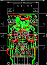
Is this the PCB for this amp?
It is. On the one hand it is far less stingy than the original and provides room for decently sized input caps. But on the other it lacks the low impedance ground plane of the "original" type board. It probably won't make any significant difference.
We can add ground plane, but maybe is better this way. There is also implemented Hybrid SCNP Network via two elco caps in non-parallel config. They can be avoided. Between SGND and PGND is a place for 10R if its needed (there is also place for jumper for direct contact).
I just finished a build based on single pair. It is playing without any noise or hum and sound wise very promising. Especially mid and highs as mentioned by others. Only issue on delivery was that transistor leads were bent very hard so they had to be bent back slightly and some solder was added in the “knee”.
DC on output moving up and down but never more that 70mV.
Changed input caps to Jantzen Superior 5,6uF which improved sq quite a bit!
I got some questions perhaps someone can advise on? I have some Exicon laterals from “The Wire AMP” build which some have advised on using for this clone. Post #86 and also this quote:
1. Can I drop in the Exicons ECW20(NP)20 without any other changes?
2. Is a bias increase possible and what is recommended?
3. I have some Caddock 200ohm laying around. Any issues replacing the series resistor of 51ohm?
4. Would sq benefit from using a supercap, or is it mainly to stabilize dc on output?
Thanks
DC on output moving up and down but never more that 70mV.
Changed input caps to Jantzen Superior 5,6uF which improved sq quite a bit!
I got some questions perhaps someone can advise on? I have some Exicon laterals from “The Wire AMP” build which some have advised on using for this clone. Post #86 and also this quote:
You are correct,
Using only one pair LMOS as output, sounding is relatively too soft, insipid. But this matter happened with Hitachi/Renesas, Exicon's single die devices.
I also used one pair, but it is dual die devices ECW20N20/ECW20P20. It's two single die device integrated inside package TO-264. That problem is fixed.
Regard,
Cuong Nguyen
1. Can I drop in the Exicons ECW20(NP)20 without any other changes?
2. Is a bias increase possible and what is recommended?
3. I have some Caddock 200ohm laying around. Any issues replacing the series resistor of 51ohm?
4. Would sq benefit from using a supercap, or is it mainly to stabilize dc on output?
Thanks
- Home
- Amplifiers
- Solid State
- Dartzeel amp schematic - build this?