Hi analog sa
Maybe I should try to change the base resistors to a higher value. I mean the base resistors for the power transistors.
At what supply voltage are you running?
Reducing the base resistors of the outputs leads to a very steep increase in the bias, so it is really hard to get a suitable standard resistor value. It is a much better plan to increase the value of the drivers' base resistors, as the corresponding increase in bias is a lot more gradual. You will need something like 10ohms in series with one of the power rails in order to monitor the change in bias.
Something which does not get talked about much is the matter of speaker impedance. The original amp has a transformer tap which drops the supply voltage down by nearly a half for 4ohm speakers. Having the power outputs so close together makes it really hard to keep them cool when working into lower impedances. Keep this in mind when increasing the bias current.
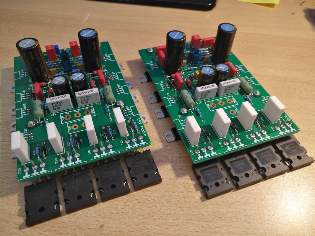
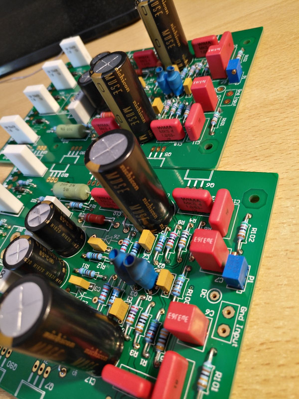
A very interesting variant of the darTZeel NHB-108 clone with two pairs of power transistors, for each PCB, that I just finished making.
Clearly having the same driver stage as the normal version, the output power is substantially identical, but the power amps working in a zone of greater linearity, return a register of "bass" with the same speed and articulation of the normal version, but much more dynamic and impact.
The changes I have made are as follows:
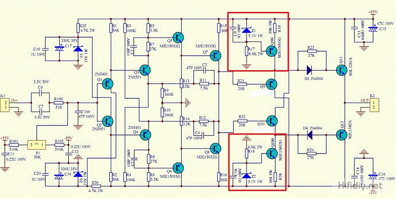
1) for a more suitable drive of the two pairs of power amps, the replacement of the two 5.1 V Zener diodes Z1 and Z2 of the "Constant Current Generator" of the driver stage originates, with others of 6.2V (maximum applicable value to avoid the saturation and distortion of the Q9 and Q10 drivers) to have a better and more adequate drive capacity of the final power stage;
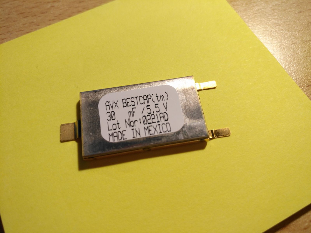
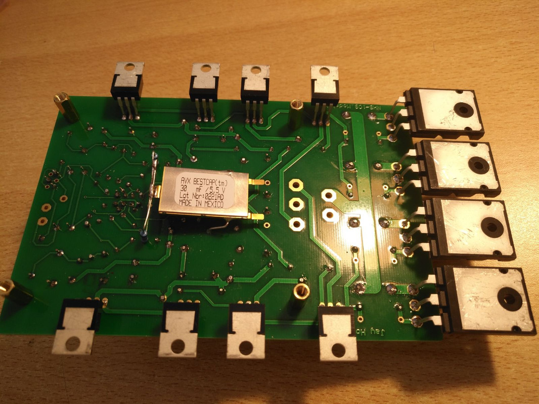
2) The installation of a Supercap with a higher capacity of 30,000 uF between resistances R9 and R10 and mass, replacing the classic 22,000 uF;
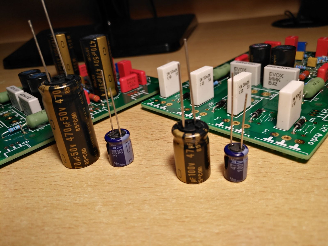
3) The replacement of the four original capacitors of ridiculous quality (C17/C18 330uF/35V and C15/C16 47uF/100V) with others 470uF/50V and 47uF/100V respectively of the excellent and extraordinarily musical NICHIKON Muse UKZ Series;
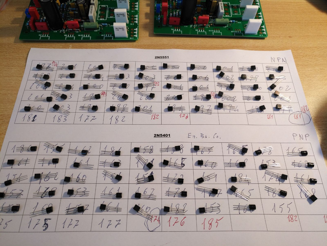
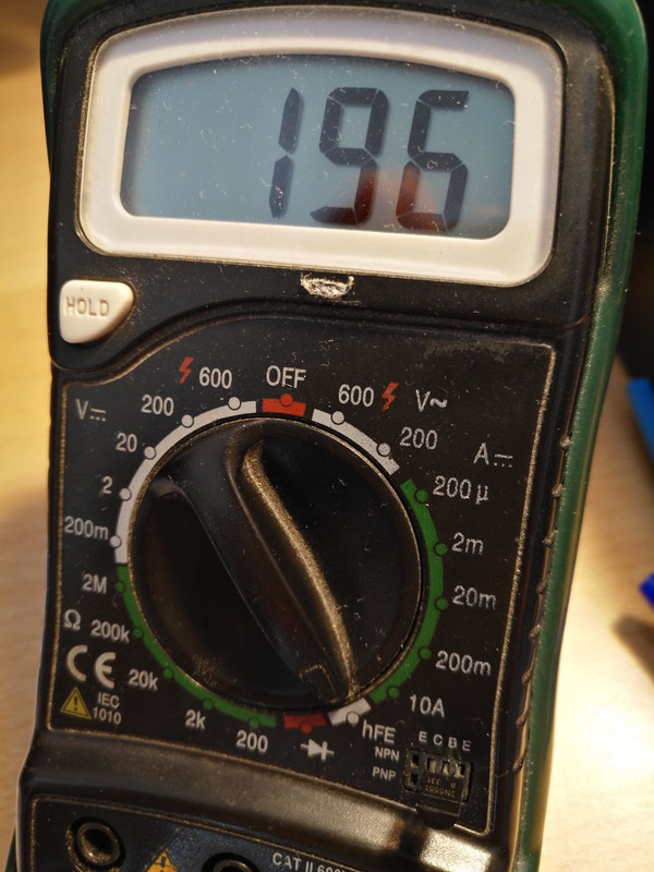
4) And finally, perhaps the most important thing of all for this exceptional circuit layout, the perfect match and coupling for HFE, of the four input 2N5551/2N5401 transistors (Q1, Q2, Q3 and Q4 that you must be careful to physically join with a little thermal paste and the heat-shrink sleeve), in order to reduce the characteristic of this design of the DC Offset output, "dancer" and unstable;
Dartzell 2x50v ac Does the transformer cause problems
Could you, please, be more elaborate.Yes I did that but still a lousy useless amp.
Is the NHB-108 itself, in general, a lousy amplifier or you fail to make yours particular amplifier as great as it should be? 🙂
Last edited:
Hi, always interesting and I will start to built mine soon.
On the four transistors version is there other modificationor adjustment than add two transistors and their own 1N4004 and 27 ohm resistor?
On the four transistors version is there other modificationor adjustment than add two transistors and their own 1N4004 and 27 ohm resistor?
There will also be the need for individual emitter resistors, something missing in the original and being one of its selling points. Adding these resistors will almost compensate the improvement in damping factor caused by the added parallel transistors.
I can't see it on the schematic emitters are connected together to the output.
witch value and power do you recommand ?
Thank you
witch value and power do you recommand ?
Thank you
I'm glad to see renewed interest this tread. For weeks, or should I say months, I have read posts here and I have learned a great deal owing to several exceptional members of this community. "Ultima legione", "analog_SA", "Domenico" and others presented here valuable information and have "infected" me with desire to build my own NHB-108. Now, I have become even more enthusiastic because my first DarTZeel sounds incredibly fine. With good speakers I have impression of sitting in the first row in Scala listening to Pavarotti, Caballé and Ghiaurov in "La Gioconda" even though the recording is ancient.Hi, always interesting and I will start to built mine soon.
On the four transistors version is there other modificationor adjustment than add two transistors and their own 1N4004 and 27 ohm resistor?
Now, I have one finished amplifier and plan to place it into a beautiful DIY chasis. I also have two pairs of boards left to make all together three NHB-108s. Two for Bi-amping and the third is present to my daughter.
🙂🙂🙂
#dugain, welcome to this tread and enjoy DIY business
#analog_sa, welcome back to your theme. I'm looking forward to learn from you more
#Ultima Legione, come back, we need your passion, enthusiasm and knowledge
#Domenico, come back, we need your expertise here.
🙂🙂🙂
I can't see it on the schematic emitters are connected together to the output.
witch value and power do you recommand ?
Thank you
The emitter resistors are always present when you parallel devices with even slightly dissimilar current gain. Customarily those are in the region of 0.22R as shown on Domenico's circuit in this thread. But of course these resistors also usually share the purpose of providing local current nfb and stabilise the operating point. Not in this circuit though, as their sole purpose here is to ensure equal current sharing between the output transistors. So, with matched parallel pairs a very low resistor value can suffice. From what I see on the pics of Ultima Thule's board above those resistors appear to be just 50mOhms. In this case their effect on the DF will be negligible.
Two for Bi-amping and the third is present to my daughter.
Thank you for your kind words 🙂
Over the last few months i have been enjoying biamping with 4 of the clones. It has worked remarkably well in my case and hopefully it will work well for you too.
A couple of words about my clones. I don't use a servo or a nfb bypass capacitor, so offset needs a periodic adjustment. At the input there is a BG-N 4.7uF bipolar. Power for the bass units comes from 1000VA transformers, Mundorf M-lytic caps and rectification is provided by LT4320 sync rectifiers. The mid/high amps are similar but with 500VA transformers per channel.
I briefly experimented with removing the input cap altogether and adjusting the input circuit for zero offset. It appears to be fairly stable provided the resistance between the input bases and ground is kept constant. A friend agreed to test this theory in the longer term, we'll see how it goes 🙂 The improvement in clarity due to the removal of the input cap and the biasing network is substantial.
On a separate note i also tried the voltage amplification part of the amp (the Revox designed part) as a line stage and seem to like it a lot. Still waiting for proper boards to arrive.
The emitter resistors are always present when you parallel devices with even slightly dissimilar current gain. Customarily those are in the region of 0.22R as shown on Domenico's circuit in this thread. But of course these resistors also usually share the purpose of providing local current nfb and stabilise the operating point. Not in this circuit though, as their sole purpose here is to ensure equal current sharing between the output transistors. So, with matched parallel pairs a very low resistor value can suffice. From what I see on the pics of Ultima Thule's board above those resistors appear to be just 50mOhms. In this case their effect on the DF will be negligible.
My Dartzeel was delivered with 50 mohm. But the amp was oscillating. I stopped buying electronics from Aliexpress.
The value of the emitter resistors and the oscillations you have experienced are likely unrelated. The only risk from the low values is unequal current sharing which in low impedance loads may be fatal.
The value of the emitter resistors and the oscillations you have experienced are likely unrelated. The only risk from the low values is unequal current sharing which in low impedance loads may be fatal.
Thanks but anyway the Dartzeel will be replaced by something else. Have some First One medium moduls. Current feedback.
The emitter resistors are always present when you parallel devices with even slightly dissimilar current gain. Customarily those are in the region of 0.22R as shown on Domenico's circuit in this thread. But of course these resistors also usually share the purpose of providing local current nfb and stabilise the operating point. Not in this circuit though, as their sole purpose here is to ensure equal current sharing between the output transistors. So, with matched parallel pairs a very low resistor value can suffice. From what I see on the pics of Ultima Thule's board above those resistors appear to be just 50mOhms. In this case their effect on the DF will be negligible.
ok well understood I will put these resistors, thank you for your explanations.
I could read that sometime you have yo adjust the offset witch evolute during the time, do you have put a system to control it in real time?
By "real time" do you mean using a servo? This has been done in Chinese and diy clones and technically seems to work great. I personally dislike servos and adjusting the offset by hand once every few months is fine by me. Not finished tweaking the amps anyway, far from it 🙂
Now, my 1st NHB-108 is resting on heatsinks, dissassembled, waiting for a brand new chasis. I have tested it on +-25 and +-55,6VDC (with +-40VAC transformer). It sounds much better on high voltage.Over the last few months i have been enjoying biamping with 4 of the clones. It has worked remarkably well in my case and hopefully it will work well for you too.
For time being I use also four separate LM3886 amps to experiment with bi-amping.
I personally can hear sounds between 35Hz up to about 15kHz and these values are just thresholds on inaudible. That means I miss almost one octave at the low frequency side and a half of the highest octave. I'm not a rare exception: many people suffer from these limitations but believe in theoretical 20Hz-20kHz. However, that's in a rear case of healthy, young ear. Capabilities, unfortunately as everything else, weaken with age. I really don't miss that lower portion but I would like to increase audibility of details buried in high tones that I can still hear. I have measured that and I am aware of my hearing limitations. Therefore, I need bi-amping, most other people should use it too.
What I want is not to let electronics »compose« high tones for me but I would like to enhance audibility of high tones to achieve what I name »presence in front of the stage« or »presence of the chamber«. Impression of spatial component of sound is hidden in these higher tones and I want to increase detail and audibility to have impression of physical presence of instruments and vocals.
Of course, I am talking about acoustic, classical instruments. The present day »virtual instruments« are another story that I really don't care about.
For example, picture yourself in front of a real piano: it has physical size, tones are created in strings spread at different locations within the instrument. I have used my NHB-108 clone to listen to »Emperor« Concerto recorded in 1973 and was astonished with details that mimic appearance that higher tones are coming from my left and lower tones from my right, just like I was standing close, in front of piano. Origin of tones was continually distributed in front of me just as in case of real piano. That isn't simple distribution left-right, but continuity. There is a similar effect with Bach concertos where instruments are beautifully distributed »in a chamber« and instruments do not jump one over another. That is a significant improvement compared to what I've heard before the NHB-108 clone.
Recently I have tried to replace my crossovers with »miniDSP 2X4 HD DAC« but that attempt has failed miserably. That box isn't close to be considered hi-fi device. I have thrown 250 EUR through window for that awful device.
Now, I am looking for another adequate active crossover. Meanwhile I will use good old crossovers built in a separate box.
By "real time" do you mean using a servo? This has been done in Chinese and diy clones and technically seems to work great. I personally dislike servos and adjusting the offset by hand once every few months is fine by me. Not finished tweaking the amps anyway, far from it 🙂
No I think to two basic vu meters but oblige to disconnect the output and install switch on the vu meters to switch it off during listening.
Another item is the loud speakers protection do you use fuse or other system ?
Regards
I have a question:I don't use a servo or a nfb bypass capacitor, so offset needs a periodic adjustment.
I couldn't find clear instructions how to adjust an offset?
What I have isn't enough for me:
I don't understand that. First, I understand that the voltage should be measured at the "DC" point, but I don't understand what is the 2nd point of measurement.first adjust the I put "DC" point potential to 0mV, and then adjust the output to within 50mv...
I am affraid to mess with the board too much to avoid possible shortcut. During measurements I have power supply connected through bulb power limiter. I also have several 22 Ohm 100W resistors to load output properly (thanks for this suggestion). However when I try to find the reference point for measurement, the measured value either varies too much or I get "open circuit" warning.
I appreciate your advice regarding this.
- Home
- Amplifiers
- Solid State
- Dartzeel amp schematic - build this?