
You can read it with a translator, especially the beginning. There is a lot there regarding boards and configuration. https://forum.ixbt.com/topic.cgi?id=95:592
I ordered a pair of PCB's as a future project. However, my plan is to modify it a bit and use it for mid or treble in an active setup, and plan to run lower voltage on rails and possibly higher idle current to increase the class A region. I don't think I need more than maybe 20V rails for my needs. I read several people mentioning it's not great for bass, and that's my experience with high output impedance amps too, so won't even bother to try that.
I saw earlier in the thread that at least @analog_sa has made a sim of the amp, and since I'm a bit lazy I thought I would ask here first if he, or somebody else would be willing to share a sim?
I saw earlier in the thread that at least @analog_sa has made a sim of the amp, and since I'm a bit lazy I thought I would ask here first if he, or somebody else would be willing to share a sim?
From what I see in post 7 and others the amp has fixed bias, it does not mean it can not be changed,
but definitively not by rotating an adjustment pot. This however is not a "high output impedance" amp,
yet surely higher as with a full feedback design.
but definitively not by rotating an adjustment pot. This however is not a "high output impedance" amp,
yet surely higher as with a full feedback design.
It has no problems with bass. I repeat, if you do it right and don’t skimp on components, especially the power supply, it will play so hard your ears will turn up. The quiescent current has a beneficial effect, if radiators allow, a supply voltage of less than 30 volts is not recommended. If there is doubts, it’s better to use another scheme, of which there are a lot, and not torment Dartzeel. I wrote about my settings for it and a comparison with the A60 clone that is in the next thread. 4 people listened to both and did not reveal the winner. I don’t want to offend anyone, but everything is necessary do it wisely and then evaluate something. Otherwise we begin to modernize, get into the wilds and say - it doesn’t play. Happy New Year, everyone.
Attachments
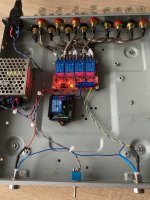
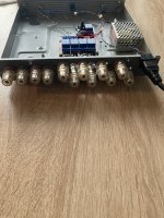
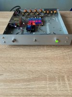
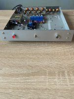
I made such a switch with a remote control, it is very convenient to compare 2 amplifiers for one speaker or 2 speakers with one amplifier. The switching is almost imperceptible to the ear. There is no need to switch cords. The cables are all the same, even the Cardas interconnects. I am writing this so that they understand .If you assemble Dartzeel, then try to make the main board as in the original. If you experiment, then we no longer call it Dartzeel.When I finally decide on the amplifiers, the switch will of course be disabled.

Attachments

Can the switching be automated, thus allowing bind testing?The switching is almost imperceptible to the ear.
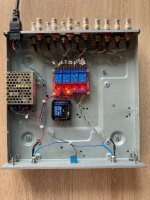
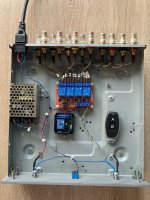
When the controller is turned off, one output is constantly connected; mine is Dartzeel. When you turn on the controller with the toggle switch, it also remains on, the red LED lights up (this is Dartzeel on the remote control, marked B). But when I press A on the remote control, the output switches to A60 (green lights up LED) in my case. The only need is that I use one pre-amplifier, which needs to switch outputs from the remote control, too, there are 2 of them. I got the hang of it and switch both remote controls at the same time.If you press B back, Dartzeel will connect again (red LED)
Here is a basic sim + Cordell models I put together for the amp. I have only checked that it seems balanced at DC so far. The only issue I know of is the Zener voltages, since I did not have models for 5.1V Zeners. It will have some effect on the idle current.
Attachments
I have done some quick sims of the diode setup in the output stage. As mentioned earlier in the thread the VAS has feedback, so most of the distortion is generated by the output stage. I think the diodes have a major influence on this, so I thought I would just compare VAS voltage with output voltage, assuming VAS voltage is correct, and the diff is the distortion generated.
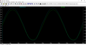
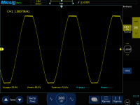
10kHz 1V input. The current through the load is to the right in the graph, diff voltage between Vas and output to the left
This is a sim of the standard setup with 4004 diodes 4 Ohm load

Comparing it with 8Ohm load:

Here is resistors only, no diodes, 4Ohm load:

Here is an example with shottky diodes with resistors in series, 4ohm load


Thoughts on this.. ?
The 4004 diodes seem to be a bit 'sticky' before they 'release' from conduction, surely that could explain bad sound at high levels. 8 Ohm load with lower currents look better No diodes looks nicest. There is some deviation around crossover, I'm guessing due to Gm doubling and mismatch between PNP and NPN characteristics? I tried to balance it a bit with different resistor values on the upper and lower half, and it seems a little bit nicer then.
Schottky diodes switch cleaner, but also switch on quite early, so I added the resistors to smooth it out. Possibly two Schottky diodes in series would work similar to the original, but with cleaner switch-off.
I think the 4Ohm test is relevant since reactive loads (speakers) will increase the current significantly even with 8Ohm rated speakers.
After reading through the whole thread, I'm still not sure if I'll build this one or not. I do have a lot of unfinished projects anyway..
10kHz 1V input. The current through the load is to the right in the graph, diff voltage between Vas and output to the left
This is a sim of the standard setup with 4004 diodes 4 Ohm load
Comparing it with 8Ohm load:
Here is resistors only, no diodes, 4Ohm load:
Here is an example with shottky diodes with resistors in series, 4ohm load
Thoughts on this.. ?
The 4004 diodes seem to be a bit 'sticky' before they 'release' from conduction, surely that could explain bad sound at high levels. 8 Ohm load with lower currents look better No diodes looks nicest. There is some deviation around crossover, I'm guessing due to Gm doubling and mismatch between PNP and NPN characteristics? I tried to balance it a bit with different resistor values on the upper and lower half, and it seems a little bit nicer then.
Schottky diodes switch cleaner, but also switch on quite early, so I added the resistors to smooth it out. Possibly two Schottky diodes in series would work similar to the original, but with cleaner switch-off.
I think the 4Ohm test is relevant since reactive loads (speakers) will increase the current significantly even with 8Ohm rated speakers.
After reading through the whole thread, I'm still not sure if I'll build this one or not. I do have a lot of unfinished projects anyway..
Attachments
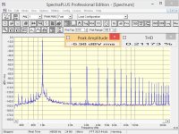
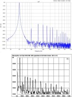
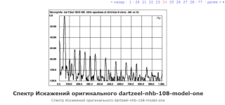
I have already published here the graphs of the Russian guys who made this amplifier. Once again I’m publishing the original and what the guys cloned. I’m not good at this, look and compare experts. If you think that Dartzeel does not have enough high frequencies, then stop trying to make it. I (4 other music lovers) compared Dartzeel and A60 on music, we didn’t feel the difference. Or is the A60 just as bad? The whole paradox is that this scheme has been in development for the second decade, but it is also sold for quite a lot of money and people buy it.🤔
Attachments

When my friend first listened to my Dartzeel clone, he didn’t say it was good or bad. He said with admiration, that’s something else.🤔
This amplifier is more or less a carbon copy of the Revox B750, the output stage is slightly different but that s about all,
not a coincidence that Dartzeel is also a swiss company, like Revox...
not a coincidence that Dartzeel is also a swiss company, like Revox...
This amp has fascinated me for years, with it's bad objective measurements (distortion), and generally positive subjective listening impressions. After listening to some tube amp with similar distortion, and thinking it sounds ok, -or actually pretty good, I have become less obsessed with distortion numbers.
However, in this thread and others, there seems to be some people complaining about tightness of bass, and also that it sounds harsh at higher levels, so I'm just trying to do some sims to understand why.
I know the output stage without feedback has high output impedance and will probably make the bass sound uncontrolled, and maybe the diodes switching makes it sound harsh at high levels. Maybe schottky diodes would be worth a listen in those cases.
After putting the device in order, it was time to listen to it. It doesn’t have enough stars from the sky, but the sound is not colored, it plays quite simply, there is a stage, but it’s a bit flat, but it’s alive, there’s at least some kind of emotional presentation, unlike its brother Revox B-251.
Overall I was not impressed with the amplifier. I think it makes sense to take it if you need to assemble a rack from Revox components. This is a description and review of the Revox B750 by the master who performed prophylaxis on it.😉Nobody told me that about Dartzeel.😏
Overall I was not impressed with the amplifier. I think it makes sense to take it if you need to assemble a rack from Revox components. This is a description and review of the Revox B750 by the master who performed prophylaxis on it.😉Nobody told me that about Dartzeel.😏
Last edited:
This amplifier is more or less a carbon copy of the Revox B750, the output stage is slightly different but that s about all,
not a coincidence that Dartzeel is also a swiss company, like Revox
Most Japanese vintage amplifiers copy each other.5 Japanese corporations had more than 40 famous companies divided among themselves (we read the literature) and dictated their terms to the whole world. The circuits have long been worked out and improved. The main thing is their implementation in hardware. If you do it on plywood, then there will be plywood .If you take it seriously, you don’t need to measure it. We make it ourselves using a good element base and compare, then either trash it or listen. Guys, there are some who like it and some who don’t. In comparison with the A60, until I raised the quiescent current for my power supply, it wasn’t very good either, after that everything fell into place. With your capabilities and the purchase of original parts, this is easy to check.This amplifier is more or less a carbon copy of the Revox B750, the output stage is slightly different but that s about all,
not a coincidence that Dartzeel is also a swiss company, like Revox...
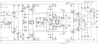
Experts, I am attaching a diagram of the Revox B750. I don’t see the similarity. Dartzeel is not like that.🙁
That s the same amp, the difference is that Revox use a shunt compensation, wich is inexistant in the Dartzeel, as well as a global NFB loop that enclose the output stage while Dartzeel enclose only the VAS with the OS being NFB less, you can also check the B750 MK II wich is slightly modded but is still using the same base schematic as the B750.
- Home
- Amplifiers
- Solid State
- Dartzeel amp schematic - build this?