Back to the schematic of post 2156 :
https://www.diyaudio.com/community/...matic-build-this.134362/page-108#post-7301304
Be it Dartzeel or not, let's assume it is a working amp or even proven circuitry.
I see a striking similarity to Audiolabor amps of about 1980 manufacture
The differences here :
I am not sure why Q11, Q12 have no emitter resistors.
My question from post 2072 is still valid, what are D3, D4 good for ?
Some gentleman can probably explain why 90% of the gain of Q3, Q4
is scaled down by resistor dividers.
https://www.diyaudio.com/community/...matic-build-this.134362/page-108#post-7301304
Be it Dartzeel or not, let's assume it is a working amp or even proven circuitry.
I see a striking similarity to Audiolabor amps of about 1980 manufacture
- input buffer instead of differential amp,
- feedback from driver output, not speaker output,
- diamond style output stage with current source drive.
The differences here :
- reduced (regulated) supply for the input transistors,
- followers Q5, Q6 added,
- offset trim instead of servo.
I am not sure why Q11, Q12 have no emitter resistors.
My question from post 2072 is still valid, what are D3, D4 good for ?
Some gentleman can probably explain why 90% of the gain of Q3, Q4
is scaled down by resistor dividers.
marigno Thank you. My Russian friend gave me the same recommendation. I was embarrassed that when cutting a track, power through a 0.1 ohm resistor will receive not only the output transistor, but also Q10 (according to the diagram). This is fine? Soldering the collector from the board of a powerful transistor is problematic.
as-audio. You still need to read the entire thread, and not only this one. There are details on the Russian site, otherwise there will be questions that have already been asked more than once. https://forum.ixbt.com/topic.cgi?id=95:592 Успехов.😉
I say the board draws about 320mA because I'm referring to the original untouched scheme.
My mods (WHA-217) make it draw a lot less.
What kind of mods has your boards?
If you have a very small amper-clamp (leaking clamp), and if it fits on the collector terminal (I don't think so), you can try to use it without having to work on the board. Pay attention: you can use the amper-clamp on both the collector or the emitter. But if you decide to use the 0.1Ohm resistor, put it in series with the collector, not the emitter, it wouldn't be exactly the same.
Any point going from a collector to its power rail is good. Choose the easiest-to-operate one.
However, let's try a different and less invasive approach: short the input and measure the current on a power rail (Itot). Now lift only one end of both the base resistors and only one end of both the diodes paralleled to those resistors; then repeat the measure (Iboard). The final stage drawing will be the difference Itot-Iboard.
However, let's try a different and less invasive approach: short the input and measure the current on a power rail (Itot). Now lift only one end of both the base resistors and only one end of both the diodes paralleled to those resistors; then repeat the measure (Iboard). The final stage drawing will be the difference Itot-Iboard.
marigno Hello. Small report. I cut the POS track and Q11 (on the printed circuit board), that is, power + to the collector. I soldered a 0.1 ohm resistor there. The voltage drop is 29mV, which means a quiescent current of 290mA. Resistors R23-24 installed by 10 ohms (in parallel 2x20 Takman). I measured the voltage drop again, it became 40mV (400mA). Removed 0.1 ohm and soldered the jumper. I drove the amplifier (the constant voltage at the output after adjustment became more stable 0) for 4 hours, under loud music. As a result: the temperature of the amplifier after the run is not higher than 50 degrees (maximum on transistors). The heating of resistors R19-20 (5W 39 ohm) is a bit confusing, their temperature is 60 degrees. In general, the sound has changed for the better. Lighter and freer or something, the bass approached Accuphace. Satisfied with the result.🙂

The hotter the better! True, but not always. The transition Class A/Class B happens at a higher volume level so it is more audible as a distortion. This is the reason why the bias should be as low as possible. But, if you like it better, and if you are used to listening to music at a volume not that loud, try with 1A bias.
Take a look at my WOTS WHA-53
https://www.diyaudio.com/community/...-a-hybrid-main-amplifier.396135/#post-7276068
Its sound is very refined because it is Class A up to 20W with 1A bias, and even because it uses only one final pair (this is very important and makes me laugh with 108s modded to have 2 or more final pairs because the best of this project is nullified). It is just warm, so I'll try higher bias asap.
You can rise the bias to very high values in order to push the transition Class A/Class B to a very high volume, hoping it will not happen; the transistors will work well even at very high temperatures (I got a blister on my finger with another amp), and also the thermal exchange works better. But you have to use a fan to move the air inside the cabinet, the capacitors don't like the heat.
About R19/R20: they configure the two CCSs at 117mA, I recommend not changing this value, because a lower current CCS will not drive properly the final stage, and a higher current brings Q9/Q90, Q10/Q100 to a higher temperature, they dissipate already a total of 25W with your voltage of 90/92Vdc. Try, if you want to, but very carefully.
Last, but important, the higher the bias, the higher the electric bill...
marigno Thank you. I stopped on my option and I will not do anything else. The temperature of 50 degrees is normal at the power that I usually listen to music. Previously, it probably didn’t rise above 35 (why it was boring). The original voltage has 56 volts voltage, and the rest current is less (R23-24 resistors by 27 Ohms according to the scheme), but according to reviews on the Internet, the amplifier warms up strongly. My acquaintance wrote that with an increase in the rest current (in my case, when powering 45-46V), you can raise, the distortions are reduced by 20 percent. He made experiments and measurements. Well, the radiators allowed to do this. Thanks again for the help. It is good when they teach and prompted without rudeness and moralizing.
When you are satisfied, you better stop! When a thing is good enough, leave it alone or it will go bad (Итальянская пословица).
There are many conflicting reports as to what needs to be done to get this amp sounding it's best........ I stopped on my option and I will not do anything else........
You compared the Dartzeel to the A60+ and it seemed to have been on paar with it. That's quite good news.
May I ask what mods you end up using?
Greets Klaus
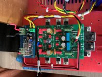
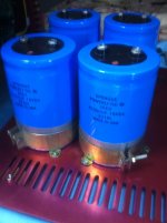
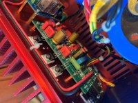
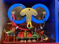
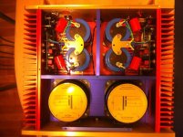
Hi. I used custom boards that are 1:1 to the original. The passive elements are original in accordance with the table that is published here. But the resistors were used by Takman Ray, the capacitors in the Sprague power supply are 67000 μF (in reality 75000) x 4 = 300000 μF. The transistors at the input are Philips, further 15032/33, 4281/4302.I increased the quiescent current by as much as the power supply of the amplifier and radiators allowed. See my messages above.
Attachments
Last edited:
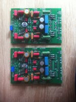
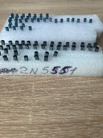
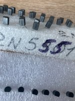
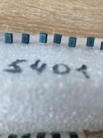
The ones heat shrinked together?.,,The transistors at the input are Philips......
Do you remember the model?
I can purchase a transformer with 750 watts 40v 0 40v but there is only one available.
Would two separate bridge rectifiers fed by one transformer get me a bit closer to real double mono?
Would two separate bridge rectifiers fed by one transformer get me a bit closer to real double mono?
Hello. The heat-shrinkable input transistors are the same, only original Philips ones. I think one winding for 2 channels is not good even if it is a 750W transformer. The concept of dual mono is lost. It is better to buy 2 transformers 250-400 W. The power supply is 40 V, already a maximum, after the rectifier 56 V.
Attachments
- Home
- Amplifiers
- Solid State
- Dartzeel amp schematic - build this?