Here is Mouser shopping cart, a pdf of the BOM and Mouser BOM that you can upload to Mouser. This is for 2 channels. Primary goal was to choose what's in stock, so feedback on alternative components is very much welcome. Especially MJE15032G and MJE15033G replacements.
https://www.mouser.se/ProjectManager/ProjectDetail.aspx?AccessID=c08a9f3ad6
https://www.mouser.se/ProjectManager/ProjectDetail.aspx?AccessID=c08a9f3ad6
Attachments

I'm having hard time matching the component list from Aliexpress with your components list @marigno The values match 1:1 but not their names/labels and in a few places the ratings don't match (yellow). Same goes for caps, so my guess that different clones use different component names. What about the ratings mismatch?Here is the list of components of the scheme here enclosed.
Attachments
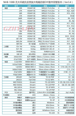
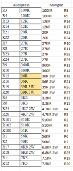

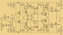
I worked hard on the NHB-108, in order to add a buffer capable of 200W. So I had to re-draw the scheme myself as a starting point for my project. The schema I posted is the original, but the component index is proprietary mine, because I used the renumbering function. I didn't care about the rating of resistors, I calculated it by myself, so, for example, the 39Ohm resistors dissipate 0.6W in heat, then a 2W ones are sufficient. The 36Ohm resistors dissipate 0.23W @+/-70V, something less @+/-50V, so I would choose something stronger than the 0.6W standard for the project, perhaps, at that time I couldn't find a good 1W ones, same to say for the two 4.7KOhm powering the zeners, which dissipate 0.26W, while the two 6.8KOhm dissipate 0.3W. You can verify all ratings by calculating them by yourself, I always do.
@piotrkundu: Because of the considerable difference in hFE between NPN/PNP MJE15032/MJE15033 transistors (lots of fakes on eBay), I strongly recommend you choose something better, you don't need such powerful devices. I used the pair 2SC4883A/2SA1859A, but they are obsolete and impossible to find. The pair 2SC4382/2SA1668 Y selection is the closest solution, check them on B+D Enterprises, which sells on eBay too as "bdentric" or a similar seller name, a reliable seller). Q5/Q6 could be 2N5551/2N5401, I used the pair TO126 TTA004B/TTC004B, they don't need to be mounted on the heat sink. In quiescent condition, the branch Q7/Q8 dissipates 8W, to say 4W/device, while the branches Q9/Q11 and Q10/Q12 dissipate 12W each, to say 6W/device. Keep it in mind when choosing new devices (check their SOA). C10/11/12/13 MUST be silver mica ones, check them on eBay. A very good solution for the final pair Q14/Q14 could be the 2SA2223A/2SC6145A multi-emitter pair, Y selection; you find on B+D Enterprises.
Hello,
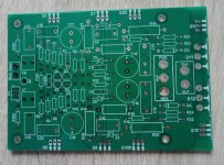
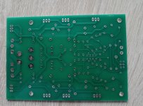
I red a lot of the normal NHB-108 clone (China) and I think its worth to try and build one. In the moment I draw the layout for the PCB to make it possible to change or add parts if necessary and make an own PCB.
Now I read about this mod and due to the above it maybe possible to change some parts on the PCB.
So, @marigno, if you or even someone else has ideas for this - please tell me - I'll do what I am able to......
In the moment I hear music with a FC-100 from @roender and normally I don't need a new amp.....
Has someone heard both the NHB-108 and the FC-100 and can tell how they compares?
Attachments
Last edited:
Thank you for letting me know about the FC100. This is a very interesting amplifier with the gain stage made out of a double differential cascode, where the second is a folded cascode. One only gain stage followed by a buffered Sziklai pair.
Very very refined.
But it has the feedback from the output, and for this reason, I would never build a thing like this.
The scheme is a really good one, both in the VAS and in the buffer, it is worth some study finalized to the complete remotion of the feedback (almost impossible), or, at least, to move it to the collectors of Q15/Q16, at the end of the VAS, thing that is a lot more achievable. However, It is out of my knowledge since you have to prevent the "super tri-scode" from autooscillate, where I was not able to avoid a normal cascode to autooscillate (Superfinale 1981).
In this case, it would win without any doubt on my WHA-217, made on the NHB-108 base.
You could also try an NSCB working mode for the final stage.
If you wish to try the adventure with the NHB-108, keep in mind that it is not that suitable to drive low impedance speakers, like my Acoustat 1+1, the driving is too weak. Adding a buffer made out of many final pairs will resolve the problem.
So the WHA-217 was born in its first edition, followed by the "CuE" and the "E2"
I have some recommendations and a new schema of my WHA-217, less fancy than the "E2" version, has fewer mods and is a lot better. Besides it, no cascodes out of control. We are not a HiFi factory, so what I keep repeating to myself is to maintain a low profile with the maximum quality.
Moreover, but this is a personal preference, I do not like much the sound of equipment with CCSs. I would limit their use in a "Virtual Battery" PSU, to feed the Zener, and in a Diamond Buffer, where a resistor is not suitable.
Let me know if you want further information.
I forgot about PCB: I do not have any suggestions for the original NHB-108 scheme. If you want to proceed with the WHA-217, there are a few mods that you can make directly to the original PCB, and you need a small added board (take a look at my post about the WHA-217 E2). A new PCB with a single-point current feedback would be the best solution.
I decided to put an end to complicate design with feedback. I'm currently working on a class A 60W Hybrid Circlotron (no feedback at all), a lot simpler and a lot better than any other conventional SS solution. I regret the fact that the idea came to me after closing the WHA-217 adventure.
There are quite a few class A amplifiers CFB/VFB that include the voltage gain stage but exclude the current gain stage from the negative feedback loop. This leaves the voltage as pure as possible but the output is not immune from the non linearities of the output stage and thus not used with class A/B amplifiers. This creates a class A amplifier with an open presentation. Depending on genre of music ,may not be suited below 300Hz unless one has proper room treatment or open baffle speakers, but maybe unbeatable above 300Hz. King of bass is not even class D. This title still remains with class A/B.
Yes, I know. But I prefer to use a gain stage with no feedback at all. I agree there is no way to obtain such a VAS with a solid-state design.
Let's look at the first tube of a Williamson: the first triode is the gain stage, and the second triode is a Cathodyne phase inverter. Add a cathode follower on both phases made out of a 6H30. Do you think this "thing" needs a feedback loop? I don't think so.
Add a current stage made out of a pair of ECW20N20 in Class A Circlotron.
This is the project I'm working on. I think there will be no bass lack.
On the other hand, I would like to revive my old idea of a paragon follower working in NSCB, made on the 108's base, modified to WHA-217. Just some minutes ago I ordered a couple of 108's PCBs. Will see. This will be interesting for @overheater who, despite his nick, has a cold!
If so, can it be better to disconnect the positive terminal from the board, and put a resistor between it and the board for testing?🙄
Without re-reading everything, is this schematic a Dartzeel circuit, if not where is the origin ? Thanks.
@Paroxod4: Yes, you are right. You want to measure how much current the final stage is drawing. So you have to disconnect one collector and insert a 0.1Ohm resistor. You cannot use a power rail, as you say in the next post, because you would measure the total drawing of the whole board, wich is not negligible at all, more or less 320mA without the final stage.
- Home
- Amplifiers
- Solid State
- Dartzeel amp schematic - build this?