Seels the trim pots values for PSU2 12V side works better to get 10V when changing only R1 & R2.
Have to check with R1& R2 for 15V to see if the trim pots values given for 12V can be kept too.
Too bad, 😭, as a lazy guy I wanted not to touch the trim pots and have a 12V + 10V and a 12V + 15V PSU2.
Have to check with R1& R2 for 15V to see if the trim pots values given for 12V can be kept too.
Too bad, 😭, as a lazy guy I wanted not to touch the trim pots and have a 12V + 10V and a 12V + 15V PSU2.
With 100dB PSRR provided by LT3045 I don't think it would make any difference 🙂why not going CRC after the bridge rather than CC? An additional say 5R / 2W resistor could spacialy fit and provide a 31Hz Fc traditional RC filtering
The only reason here to put a small resistor between didode brige and cap is to protect the diodes from high startup current. But the caps are not too big so should be ok without it.

Thanks for the replies
I thought space would be the issue
Yep ps réfection is good already but while at it
I thought space would be the issue
Yep ps réfection is good already but while at it
I do not see how it is applicable
zobel before the primary or after the secondary ?
These values are buried somewhere in the thread.Hi miro,
I try to find out from this thread to populate a new PSU2 board for different voltage. Would like to find the values for 10V and 15V.
Question please: how should I choose the trim pot values ? Do you think some values of the pots could allow more than 1.5V trimming ? 2V margin will be better for my application. More trim turns reference needed perhaps ???
AD811 & OPA981 on the bench but I need some Volts.
Thanks,
Edit : how compare the output impedance of your board above VS the PSU2 please ? comon mode rejection ?
There is calculator and you can use it. It is based on datasheet.
Working with this calculator is not very convenient
 Sometimes you need use some website tool where you calculate parallel resistor values (because trim pot is parallel with resistor).
I am not sure about the reply on the impedance 😕
Attachments
R1 and R2 in the calculator are not referenced to R1 and R2 in schematic 😀
for LT1963A:
R1 in the calculator is R8 in the schematic, but
R2 in the calculator is parallel combination of R7 and TR1+R15
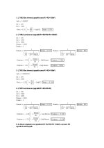
for 10V, you will have regulation 8.5 up to 11.5V (that is 3V regulation with trimmer)
first you estimate in calculator some value as voltage "minimum", now it is 8.5V:
let R1 = 330R
find 8.5V in the calculator with changing R2 = 1990R
now find maximum with R2 (11.5V):
R2 = 3080R
you know that R2 is the parallel combination and you need regulate the value between 1990R and 3080R
so you need find some reasonable combination of resistors and trimmer, ask chatgpt 😀
"I have this combination of resitor values: R7 is parallel with series of TR1 + R15, TR1 is trimmer. This combination must give values between 1990R and 3080R, set with TR1. How to choose reasonable resistor values for these components?"
and you will get the result 😎
If you prefer lower TR1 values:
Is that correct? I am not sure, you need to try 😀
Or use again the calculator and verify both extremes with sugested values 😉
for LT1963A:
R1 in the calculator is R8 in the schematic, but
R2 in the calculator is parallel combination of R7 and TR1+R15
for 10V, you will have regulation 8.5 up to 11.5V (that is 3V regulation with trimmer)
first you estimate in calculator some value as voltage "minimum", now it is 8.5V:
let R1 = 330R
find 8.5V in the calculator with changing R2 = 1990R
now find maximum with R2 (11.5V):
R2 = 3080R
you know that R2 is the parallel combination and you need regulate the value between 1990R and 3080R
so you need find some reasonable combination of resistors and trimmer, ask chatgpt 😀
"I have this combination of resitor values: R7 is parallel with series of TR1 + R15, TR1 is trimmer. This combination must give values between 1990R and 3080R, set with TR1. How to choose reasonable resistor values for these components?"
and you will get the result 😎
Final result with these values:
- R7=4.7 k
- R15=1.0 k
- TR1: adjustable from ~2.5 kΩ to ~8 kΩ
- Use a 10 kΩ trimmer for some headroom.
Alternative combos:
If you prefer lower TR1 values:
- Try R7=3.3 k, R15=470 R
- You’ll get a TR1 range around 1.5k – 5k, then you could use a 5k trimmer.
Is that correct? I am not sure, you need to try 😀
Or use again the calculator and verify both extremes with sugested values 😉
After verifying the second values in the calculator:
R7 = 3.3k
R15 = 470R
5k trimmer set to minimum = 0k
parallel of 3.3k // 470R = 411R
calculator result = 2.7V 😀 so it is bad ... now you see that R15 can not be 470R, because resistor network must be closer to 1990R, so f*u*c*k chatgpt and calculate it manually 😀
R7 = 3.3k
R15 = 470R
5k trimmer set to minimum = 0k
parallel of 3.3k // 470R = 411R
calculator result = 2.7V 😀 so it is bad ... now you see that R15 can not be 470R, because resistor network must be closer to 1990R, so f*u*c*k chatgpt and calculate it manually 😀
Last edited:
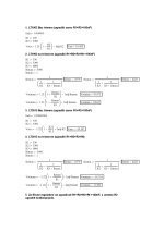
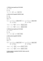
minimum 8.5V :
R7 = 3.3k ... note that this value is higher than the minimum value from network combination (1990R)
R15 = 4.7k ... this value will make the R7 smaller (and thus the final network combinaiton will be closer to the 1990R)
TR1 = set to min = 0
= parallel network ( 3.3k // 4.7k ) = 1930R (which is very close to 1990R)
maximum 11.5V :
R7 = 3.3k
R15 = 4.7k
TR1 = set to max = 5k
= parallel network ( 3.3k // (4.7k+5k) ) = 2462 (which is too low, you need 3080R)
... increase TR1 to 50k (because you need be closer to the 3080R in the resistor network)
= parallel network (3.3k // (4.7k + 50k) ) = 3110 (which is very close to the 3080R) ... here the final values from mirogpt:
R7 = 3.3k
R15 = 4.7k
TR1 = 50k
Last edited:
yup, worked on it with Excel, my goal is to see if I can just swap the two fix resistors in your board and keeps the pots as I have not an air soldering station (it is a painfull whith basic soldering station). Thanks for the tips, I go to the work table work table rigth now ! 🙂
I remember @Joseph K told be also the op828 needs some volts and i worked a lot with the stock PSU2 as I tested a lot with buffer after a 9631 op as I/V staying in the 5V (so one side for the 12V of the AD1862 analog side and the 5V of the other side to the op amp 9631 + Buff.
Time to try 12V + 10V (AD811) & 12V +15V (opa981 -works fine already with 5V); opA828,.... AD811 (but I am in smd size; 12V should be the max not insane limit!)
Still need one my two PSU2 boards for the op861 though (5V) so should at least populate a third board ! So time to try the 10V to benchmark the AD811 vs 12V.
Edit :Yes, I refered R1/R2 relatives to the datasheets of the regs (R7/8).
Last edited:
So for now I just changed R1 on both - & + rail of the 5V side of the PSU2 : 150 ohms for the + 10V and 4k3 for the -10V. Have not firered yet as I was tired. So all the 5V R2 network stays the same of the previous 5V
I will measure it non loaded... as I'm a little afraid, although the LT regs are plenty of protections...
I will measure it non loaded... as I'm a little afraid, although the LT regs are plenty of protections...
Hi miro,
That's odd, the new R1 value 4k3 on the -5V side of the PSU2 with the R2 network as per the original BOM is working okay : I measured -12V instead of -5V and can trim to -10V
But 150R as R1 for the positive rail instead of 330R make the positive fuse blowing whatever the trim pot is at zero or at max of its value ! Have to compute again by playing only with the fixed resistor to try to keep the trim pot that is hard to desoldring...
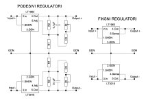
I made myself mathcad sheets for PSU2 with LT1963/3015 in various variants (with and without fine voltage adjustment), only everything is in Serbian. I can translate all, but I believe hardly anyone uses mathcad these days. 🙄
I should have made excel sheets, that would have been more useful probably,
Fixed regulators LT1963/3015 can also be installed on PSU2, resistors R1, R2, R3 and trimmer RT are not installed, 100nF cap is not installed, only a jumper is installed instead of R2.
I should have made excel sheets, that would have been more useful probably,
Fixed regulators LT1963/3015 can also be installed on PSU2, resistors R1, R2, R3 and trimmer RT are not installed, 100nF cap is not installed, only a jumper is installed instead of R2.
Attachments
Last edited:
R3 should be 5K (the pot) and not 2k2 for the +5V of Miro's PSU2 as per your first jpg.
The r1 and R2 and R3 could not be the same for the LT3015 (sees Miro's shematic).
In my compute with the R2 network I given, I only take care of the final R2 value by additionning the pot and the R below in serie then take a // resistors calculator to have the final values of R2 like if it was alone. The value took care of the pot to be at 0R and at its max R.
For the 3015, final R2 network with just the R1 changed at 4k2, will be 27791 ohms and 46493 ohms according min or max of the trim pot, supposed to give 9.2V to 14,7 V .
For the LT1963 which doesnt work with my value of R1 = 150R (blows the fuse on the positive rail for both positive regs of miro's PSU2) the R2 network is supposed to be 937 ohms and 1250 ohms for 8,7 V & 11,4 V according the pot min to max.
Last edited:
- Home
- Source & Line
- Digital Line Level
- DAC AD1862: Almost THT, I2S input, NOS, R-2R