A question for the group. How difficult would it be to modify Miro's CPLD code that converts I2S to PCM so that it went directly from SP/DIF to PCM?
I have the devices and the programmer and am planning to attempt to learn Miro's CPLD approach.
I have the devices and the programmer and am planning to attempt to learn Miro's CPLD approach.
For the AD1862, conversion is triggered by wordclock, not bitclock. After the combinatorial logic you reclock the wordclock.Early in my programming career I worked for a start-up that made IBM compatible mainframes. The chief engineer there liked riddles. For example, "When is a clock not a clock?" "When is passes through combinatorial logic." The idea being, the logic gates destroy the integrity of the clock.
In addition to damaging the clock signal, Stop-Clock introduces significant Fs noise into the system.
(I think the designers of the PMD100 digital filter knew what they were doing, they chose to implement the stopped clock conversion).
First of all, you need a FPGA. It's not easy, imo (I haven't done it).A question for the group. How difficult would it be to modify Miro's CPLD code that converts I2S to PCM so that it went directly from SP/DIF to PCM?
I have the devices and the programmer and am planning to attempt to learn Miro's CPLD approach.
https://github.com/jwhitham/spdif-bit-exactness-tools/tree/master/fpga#input-decoder
@hirscwi, do you really have to ask? Is BCK an important clock your the system? Yes. Is a multiplexer combinatorial logic? Yes.
But that's beside the point, because the clock had already gone through many logic gates during the creation of the I2S signal. I2S is the worst digital transport protocol ever foisted upon ignorant audiophiles.
But that's beside the point, because the clock had already gone through many logic gates during the creation of the I2S signal. I2S is the worst digital transport protocol ever foisted upon ignorant audiophiles.
Thanks for your answer. It makes sense to me. But is there a good way to have multiple inputs to the DAC, given that I2S is a protocol that's in common use?@hirscwi, do you really have to ask? Is BCK an important clock your the system? Yes. Is a multiplexer combinatorial logic? Yes.
But that's beside the point, because the clock had already gone through many logic gates during the creation of the I2S signal. I2S is the worst digital transport protocol ever foisted upon ignorant audiophiles.
Thanks for the link. I didn't understand all of it but it was helpful. I'll try to dredge out my coding skills and give it a try.First of all, you need a FPGA. It's not easy, imo (I haven't done it).
https://github.com/jwhitham/spdif-bit-exactness-tools/tree/master/fpga#input-decoder

If you are concerned about clock quality, use USB or Ethernet. Neither transmits the sample clock: the DAC uses a local clock.Thanks for your answer. It makes sense to me. But is there a good way to have multiple inputs to the DAC, given that I2S is a protocol that's in common use?
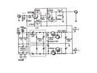
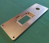
The power supply is a clone of the X-10D, but the schematic is not, it is different. Neither is worth it for this DAC.That looks like a Musical Fidelity X-10D Buffer clone board.
If it is, no voltage gain in that circuit.
Attachments

@MrHifiTunes ,I wonder what is a suitable I2S converter that you can use to skip the shift registers? (I'm a bit afraid to solder those)
I have not tried this , but this USB-I2S interface by @eclipsevl will also allow you to skip those shift registers on the DAC board:
https://www.diyaudio.com/community/...put-interface-york.413504/page-2#post-7773335
Take a look at post #10 in the thread.
It is easy to solder shift registers. Lot of flux and a flat solder tip.
https://www.google.com/search?clien...ate=ive&vld=cid:9d08b57a,vid:fYInlAmPnGo,st:0
https://www.google.com/search?clien...ate=ive&vld=cid:9d08b57a,vid:fYInlAmPnGo,st:0
Last edited:
I soldered an opa1611 with flux.
It's not working properly as the flux goes under the chip and made bad contact when it's heating up. For 10-20 seconds everything works fine after the problem starts.
An other one I soldered without flux works without a problem.
Beter have good solder then using flux I guess
It's not working properly as the flux goes under the chip and made bad contact when it's heating up. For 10-20 seconds everything works fine after the problem starts.
An other one I soldered without flux works without a problem.
Beter have good solder then using flux I guess
If you are into DIY audio projects, you will have to learn the skill... Can't avoid it forever... more and more parts are transiting to smd packages only.
VERY interesting project! Thanks for the link
I tested it today, it works as expected 👍 😊Fellows, did anyone test Miro's mini PSU boards?
- Home
- Source & Line
- Digital Line Level
- DAC AD1862: Almost THT, I2S input, NOS, R-2R