Just curious, what could possibly destroy a DAC chip? Reverse connection of power supply rails to it?
Try to wiggle it in the socket a bit more.
Zoom, if there is excess V on the iout pin, it can be fried.
Zoom, if there is excess V on the iout pin, it can be fried.

Since you are in EU, this could possibly be the most cost effective for you:@rehanabid it's all there, at this point I suspect I burned the two DACs (at the same time? Quite strange?)
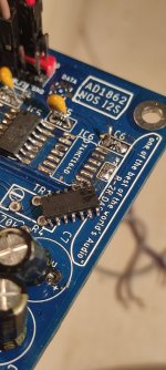
This are the resistances I measure.
Has someone a couple 1862 to sell? 😭
https://www.diyaudio.com/community/...d1865n-j-dac-chips.368012/page-8#post-7734229
@Paddy Garcia
Tried everything now, nothing to do...Try to wiggle it in the socket a bit more.
Zoom, if there is excess V on the iout pin, it can be fried.
I unsoldered all the components around output opamps, checking 3x that I didn't pulled out necessary ones.
I remember in the new configuration (actually put everything into a case, so had to dismantle and remount everything), one channel was working, then it stopped.
The other channel never worked.
I can try to resolder opamp components, also if it won't be useful at all
But the thing is, what should I see with the scope at pin 11, DAC output?
One is surely fried, it has 5Vdc at pin 11. My bad.
Ok, so there may be several reasons. If you didn't remove dac chips when soldering, esd could have had it's way with it. Trough soldering iron tip, V could have escaped into the board. When you've put it in the case, you may have somehow short circuit it. 5V on iout does lead to chip malfunctioning. The other chip that has nothing on iout, can actually mean it's ok if it's not doing conversion for some reason. First check for some obvious signs of short circuit. Re measure supply pins on socket without the chip.
Ok, used the shotgun approach, desoldered everything and resoldered in a new PCB.
Values are spot on for the right part,
in the left part appears something quite strange: the data pin has 5Vdc, going back on the schematic, jp2 (jumper) has 5V, pin 13 of the last shift register has 5V. No soldering shorts with pin 14 (Vcc) though. Perhaps the last shift register is not working (strange, because I re-soldered them random, not respecting the order of previous board).
At this point should try with another shift register, (mouser waiting time), but the big question is if 5V on the DAC data pin were enough to fry it?
I'll keep you posted.
Edit: swapped position of two shift registers each other: what happens, is that the 6th one, the last, instead of having 1.26 Vdc typical of data signal, has 5V in all pins. So does jp2 and DAC data pin. What's happening, I have no idea.
I reversed once in the past and DAC survived, but capacitor exploded ... always wear protection glasses during testing 🤣Just curious, what could possibly destroy a DAC chip? Reverse connection of power supply rails to it?
I never tried it, so it is impossible to say something about it 🙂
Of course I test with player on and data signal!@Michelag Is it same when you connect USB/I2S device? And what after disconnecting it? ... You can desolder all shift registers and solder one and measure it, add next and measure and so on 🙂
It's exactly what I'm doing, at pin 13 I should get around 1.26V which go to next pins 1 and 2. Here happens that the last one gets 5V at 1&2 from previous pin 13, so outputs 5V at data pin.
Unfortunately didn't order more shift registers...
Let me do 1 by 1
Just curious, what could possibly destroy a DAC chip? Reverse connection of power supply rails to it?
In the same position as Mike here with a pair of fried 1862's, I swapped out some caps and got C8/C18 on 12V rails wrong way round. They bulged slightly.
The DAC chips now overheat alarmingly quickly, pulling a lot of current from the PSU. Even the transformer overheats.
@Michelag you are welcome to my working 1862 board here to test with until we get some new chips.
Some better news around here, the R-Core arrived for Grunfs' and Mikes' tube IV stage, also got some replacement PCM58P chips as the last pair did not sound good, the new ones sound better. My Amanero also decided to fail, windows will not see it in the devices list. Using a spare AliX XMOS U208 module, I feel the Amanero sounds better.
So the tube IV stage with AD1865 is brilliant, haven't even tried it with the flagship PCM63 yet or the PCM58. I can yell you, so far, this little tube kit is worth every penny. Luckily Mike selected a fine Russian tube which may be having a significant effect.
The AD1865R really is an excellent value DAC chip, can be made to sound very good indeed and is so simple to power, a 5VA transformer is fine for a single DAC.
The PCM58P is also an incredible DAC, I did not recognise my speakers, the sound is huge, I have no idea they could produce such solid bass. How does this 18bit DAC produce such low frequencies? Abraxalito's kit is such value for money, his PCM58 DAC kit is tailor made for the DARK LED IV. Together they are a hell of a combo.
For balanced could we use 2 Miro dac and just flip gnd and pos out on one boardIn a nutshell - take in i2S signal (3 selectable inputs) and output PCM (with inverted PCM too for balanced DAC) so that one can feed to dac direct without the glue logic, reclock for low jitter etc.
I see a lot of flexibilities on this board, as what Miro mentioned in his notes.
So one board for post on for neg?
Instead of inverting data?
- Home
- Source & Line
- Digital Line Level
- DAC AD1862: Almost THT, I2S input, NOS, R-2R