hi Patrick, Yageos are even quieter in noise floor than the Dale cmf... I like the RN60 but bulky ! Yes of course, the best as always is to try, thanks for your tips. The smd Sussumu should be used in theory for the I2S lines as anti bouncing resistor VS through hole. the low heigth of smd as its reduced inductance cause the short length reduce the vertical RF loop with the gnd return trace/plane beneath. Theory... let your ears judge as always 🙂 smd is not always the parangon as we mostly deal with frequencies below 20k hz.And Miro wanted it through holes for maximum diyers profit.
Btw if some people try my tip on the I/V resistor and like it as I did, let us know 🙂
Hi @miro1360, on your last shematic, the crossing 22 ohms across another I2S signal is imho to avoid as well.
Btw if some people try my tip on the I/V resistor and like it as I did, let us know 🙂
Hi @miro1360, on your last shematic, the crossing 22 ohms across another I2S signal is imho to avoid as well.
Last edited:
Thank you for the heads up Miro, I will make cup coasters out of these pcb’s.Guys, please don't build this PCB, I already discovered major mistake 😱
Sorry for any inconvenience 🙁


Not the worst use I've ever heard of for trash PCBs!Thank you for the heads up Miro, I will make cup coasters out of these pcb’s.
AD1862 Stop-Clock
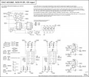
Corrected PCB, hopefully without mistake 🤐 (the mistake was in the LRCK, for the left channel it must be inverted).
It incorporates the Stop-Clock system. What does that mean? Simply: The BCK (clock) is off while no data are present for DAC chip.
Only 4 digital chips are on the PCB. The simplest stop-clock as it gets from my "studio" 🤩 The only drawback from this simplicity may be a channel shift by 10ns (because I left out the 32-bit buffer).
(I shifted channels in audacity by 100ns (10x worse scenario) and I hear no difference, so this shift should not cause any problem.)
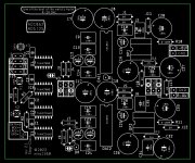
Another "major" change is in the ground plane on the PCB. I divided the GND plane for digital and analog with thick cut lines. This helps eliminate potential digital interference and can have another positive impact on the sound 🤩
BOM example: https://www.mouser.com/ProjectManager/ProjectDetail.aspx?AccessID=c547c05bf3
note: I/V OpAmp in BOM is LM7171, you can buy another one
The PCB is not tested ... (maybe even more coasters to the collection LOOOL 🤣)
Corrected PCB, hopefully without mistake 🤐 (the mistake was in the LRCK, for the left channel it must be inverted).
It incorporates the Stop-Clock system. What does that mean? Simply: The BCK (clock) is off while no data are present for DAC chip.
Only 4 digital chips are on the PCB. The simplest stop-clock as it gets from my "studio" 🤩 The only drawback from this simplicity may be a channel shift by 10ns (because I left out the 32-bit buffer).
(I shifted channels in audacity by 100ns (10x worse scenario) and I hear no difference, so this shift should not cause any problem.)
Another "major" change is in the ground plane on the PCB. I divided the GND plane for digital and analog with thick cut lines. This helps eliminate potential digital interference and can have another positive impact on the sound 🤩
BOM example: https://www.mouser.com/ProjectManager/ProjectDetail.aspx?AccessID=c547c05bf3
note: I/V OpAmp in BOM is LM7171, you can buy another one
The PCB is not tested ... (maybe even more coasters to the collection LOOOL 🤣)
Attachments
-
diyAudio_AD1862_DAC_v2.1_Stop-Clock_2022-05-28.zip657.1 KB · Views: 179
-
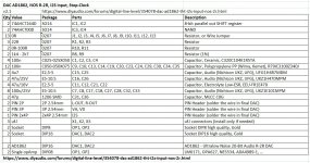 diyAudio_AD1862_DAC_v2.1_Stop-Clock_BOM.jpg209.1 KB · Views: 258
 -
 diyAudio_AD1862_DAC_v2.1_Stop-Clock_parts.jpg220.8 KB · Views: 315
 -
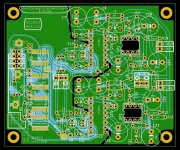 diyAudio_AD1862_DAC_v2.1_Stop-Clock_PCB.jpg411.3 KB · Views: 356
 -
 diyAudio_AD1862_DAC_v2.1_Stop-Clock_Schematic.jpg465.3 KB · Views: 356
 -
 diyAudio_AD1862_DAC_v2.1_Stop-Clock_Simulation.jpg210.6 KB · Views: 316
Miro, great work! I am impressed that you could again reduce the amount of ICs - but this circuit is not the one you posted half a year ago... I did test that one for you, see here.
...
The only drawback from this simplicity may be a channel shift by 10ns (because I left out the 32-bit buffer) 🤣 ... but as I wrote, I tested the channel shift in audacity by 10x worse scenario and I did not hear any difference.
Go with AB bigger watts. For me on Aya the best sound that I got is frm Shinkoh it bettered the Rhopoints.Hi Sumotan, Mine is EB1521 Allen Bradley...1/2W so.
Cheers
Hi Sumo...Go with AB bigger watts. For me on Aya the best sound that I got is frm Shinkoh it bettered the Rhopoints.
Cheers
I am really sad not to have Shinkoh and Riken resistors..
Thanks.
Last edited:
It incorporates the Stop-Clock system. What does that mean?
Miro, would you be please so kind and have a look at #3957...?
Hi, guys! What do you think about AD1865 (post 1431)? - what it sounds like? Can it be compared with 1862 and PCM1702? I can try to build too if sound is high class)
Still waiting chip for replacement from ali...
Still waiting chip for replacement from ali...
Don't be Rikon did not work well for Aya . LolHi Sumo...
I am really sad not to have Shinkoh and Riken resistors..
Thanks.
After some minor changes to my 1862 dac I’m listening again. I have a number of opamps to audition but have begun with LM6171. Previously I’d experienced some scratchyness during playback but that seems to be gone now. I’m not sure exactly what caused it but I suspect not having the 1862’s seated completely in their sockets as a likely contributor.
It’s very challenging to just leave the original design alone and just listen, which is what I’m trying to do.
Thanks
It’s very challenging to just leave the original design alone and just listen, which is what I’m trying to do.
Thanks
Attachments

I think your setup is good. Pan FC, stacked digital frontend, r-core, etc... You can assume it is good to be boxed .... 🙂
Bad advice that you giving Diyiggy.I think your setup is good. Pan FC, stacked digital frontend, r-core, etc... You can assume it is good to be boxed .... 🙂
Output stage should go DHT. Lol
Dht is not an oap... you can imagin all sort of things. Not the same price and hassle as well than the DHT journey..
Woodturnerfran liked DHT, but also discrete transistors. What I like is to avoid output traffos and output caps...Although I have an IHT to come with a good quiet NOS tube
Woodturnerfran liked DHT, but also discrete transistors. What I like is to avoid output traffos and output caps...Although I have an IHT to come with a good quiet NOS tube
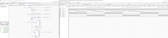
I did 🙂 This system with flip-flops is not "re-clock" but more like "re-align" data. It is not solution for eliminating jitter - in our case the most critical signal for AD1862 - the LRCK. When the source outputs jittered LRCK, it stays jittered also after the flip-flops. If you want true reclock, then the LRCK must be generated from a new clean clock (like 44.1kHz or 48kHz) and this LRCK should synchronize the I2S data (it can be complicated).Miro, would you be please so kind and have a look at #3957...?
... for generating new LRCK from a clean clock a ripple counter can be used (see the 74HC4040) https://pc.watch.impress.co.jp/docs/2004/1005/nidac_ah7.jpg
https://tinyurl.com/2zr7wcff 😎
... better as delayed LRCK can be delay other data and the LRCK left as clean as possible (for the AD1862), ... this can be job for CPLD ... what do you think?
Last edited:
- Home
- Source & Line
- Digital Line Level
- DAC AD1862: Almost THT, I2S input, NOS, R-2R