soonmo, nice work! is r3,r8 = 470k really needed, since you have the iv resistor installed?I'm using 6n23p. I ordered from jlcpcb. Circuit and gerber files are from @gaszto.
I put sun-con hybrid 120uf.Sorry Tamra, I still wanted to ask what series are 4 blue polymer capacitors at 100 uF.
Thank you.
https://www.sunelec.co.jp/jp/search/detail/?id=2921
Rubycon pfv 47uf
https://www.digikey.com/en/product-highlight/r/rubycon/pfv-series-capacitors
I have Rubycon pzf 50v 100uf and 47uf.
Its a little too big for PCB but didn't find smaller voltage ones at local shop.
R3 and R8 are grid leak resistors. The circuit is working without those resistors, but for safety reason, I usually use them. The I/V resistors are too small to help to avoid thermal runnaway of the tubes.soonmo, nice work! is r3,r8 = 470k really needed, since you have the iv resistor installed?

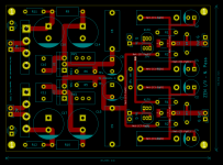
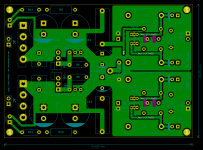
I made a little Zen IV board with simple 317/337 PSU for my miro dac. Just wanted to make something small and self-contained. This was my first go at a discrete IV implementation, and I'm really loving the sound. The boards need a couple small revisions (namely the jfet silkscreens need rotated 180deg) – if anyone has other improvements I could make, let me know (I'm a complete novice so won't be offended 🙂 Thinking I'll do a discrete diode version for the PSU next go around. After that, I want to explore some of EUVL's IV solutions.
Attachments

Super cool work Cody!
Hmm…. I do have spare “fancy” JFET’s in the parts stash
Hmm…. I do have spare “fancy” JFET’s in the parts stash
1. The Zen IV has rather limited gain. The Riv is only 500R. With 1mA DDAC current, full swing is only +/-0.5V.
2. The ZEN IV has zero PSRR, so any noise from the power supply goes to the output. Coupled with the low gain, supply noise is critical.
3. Electrolytic caps always have leakage current. I personally would use WIMA MKS2 10µ for C2, C4.
But most important is that you are happy and satisfied with the results.
Cheers,
Patrick
Thanks @EUVL, those are good notes! I'm glad that you saw this, as I was just looking at your Cen and Sen IV's. I really like the approach of these and am thinking I'll breadboard the CEN next. Regarding the ZEN, your PSRR remark is of specific interest, as I do detect a bit of light hum at higher gain (don't think its the pre). I also increased the Riv of the Zen to address the low gains you mentioned, which means increasing the supply voltage and exacerbating the PSRR issue. So, some tweaking on my part before I'm completely satisfied. Thanks again for chiming in Patrick!
You will probably see the pics below and think ole Fran here is losing his marbles (whats left of them) and posting something about an old not-high-end vintage Hitatchi receiver in the wrong thread...... but nope, its in the right place.
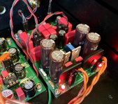
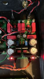
A friend of mine asked me to put a miro DAC together. This one is the most complicated build I've done yet as the inside will show. He wanted something that looked different than a home made box, or a standard chassis from modushop.... so he sourced an old receiver that was cosmetically good, but not vey high end. I gutted it, keeping the dial lights and restringing the tuner dial. None of the switches do anything except for the power switch, but they look OK!
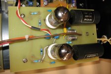
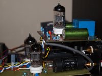
So this one is miro DAC with PSU, feeding a 3a5 DHT output stage which is powered by Ale Moglia's gyrator and filaments by Rod Coleman regulators. The 4 sources are a wm8805 SPDIF/toslink receiver, amanero USB, 8675 bluetooth receiver and an SD card player. I used a 4 way i2s switcher to switch between sources into the DAC - and mounted a little momentary button on the front panel where there was a microphone jack to cycle through the sources. Power is via 3 r-core transformers mounted vertically on the left hand side, and the DHT supplies are mounted vertically on the right hand side. Its a mess of wires at present as I soak test it for a while but I'll tidy them up eventually.
I thought I'd post it as something a bit different on the chassis. Biggest challenge was getting everything to fit inside while keeping all the AC as far away from signals etc as possible, that took several mock ups and trial fits. The SD card player is mounted vertically on the back wall which was the final key to save a lot of space.


A friend of mine asked me to put a miro DAC together. This one is the most complicated build I've done yet as the inside will show. He wanted something that looked different than a home made box, or a standard chassis from modushop.... so he sourced an old receiver that was cosmetically good, but not vey high end. I gutted it, keeping the dial lights and restringing the tuner dial. None of the switches do anything except for the power switch, but they look OK!
So this one is miro DAC with PSU, feeding a 3a5 DHT output stage which is powered by Ale Moglia's gyrator and filaments by Rod Coleman regulators. The 4 sources are a wm8805 SPDIF/toslink receiver, amanero USB, 8675 bluetooth receiver and an SD card player. I used a 4 way i2s switcher to switch between sources into the DAC - and mounted a little momentary button on the front panel where there was a microphone jack to cycle through the sources. Power is via 3 r-core transformers mounted vertically on the left hand side, and the DHT supplies are mounted vertically on the right hand side. Its a mess of wires at present as I soak test it for a while but I'll tidy them up eventually.
I thought I'd post it as something a bit different on the chassis. Biggest challenge was getting everything to fit inside while keeping all the AC as far away from signals etc as possible, that took several mock ups and trial fits. The SD card player is mounted vertically on the back wall which was the final key to save a lot of space.
I'm glad to see tubes instead of op.amps, just keep going.I built your Tube Output Stage today and connected it to the AD1862. I'm happy to hear that I prefer the sound over the OP stage. The mid-range voice are especially attractive to me. Thank you.
I used a similar scheme in my first DAC some fifteen years ago. Then I had two great mentors who were doctors for tubes in Croatia, unfortunately they are no longer with us today.
The first thing they objected to was the operating point ECC88 / 6N23P, with 1K in the cathode I ended up at 180R and a current over 10mA. This will be especially pronounced in SRPP junction without output buffer because SRPP itself is quite sensitive to the impedance of the next stage, in fact it should be calculated for a certain output impedance.
That's why I added an output buffer, simply cathode follower with ECC88. It was a big improvement. I played a bit with the tubes and in the end I chose the Ei ECC88 between 6N1P, 6N23P, Tesla PCC88 and Ei ECC88 which I still use today in the DAC in the output buffer.
For me, it was a big leap from op. amps and since then I haven't soldered a single op.amp on the signal path.
Finally, I enclose the scheme that I later used instead of SRPP, it is still a much better solution because you can go with a lower IV resistor and the sound itself was much better then SRPP.
Attachments

I have a pre amp with 3a5 after the dac.
Can I omitt the opamp and use a 2k resistor to grund,and take the signal direkt from The dac?
Can I omitt the opamp and use a 2k resistor to grund,and take the signal direkt from The dac?
Hi,
I gave the thermonic valve Loesch pdf above in a post but sorry do not remember the number of the post. If someone interested it is the revised version.
@Grumpf, any input about a 6np23 but EV (low noise) version from 1973 to 1985 ? versus a nos ecc88?
If low noise as a E188CC what do you think about only one tube for both channels, i.e. just I/V a la Thorsten Loesch w/o grid stopper per the shematic he gave for the tda1541 (but with the good value for the R i/v of course) VS SRPP?
How much volts point did you choose for the 6np23 please ? 70V?
Do we really need a buffer with a high impedance pre/amp 25k input or more ?
If anyone please had gerbers for a gyrator and/ or colemann HV type reg it will be very appreciated 🙂

Well, I am using that same circuit (although mine has filament bias) as you are, and I have built some with the black board from aliexpress that you have as well. What I'd suggest is to pull the opamps from their sockets, and stick a suitable resistor (sized for gain, maybe start with 1k) into pins 6 and 7. Connect one side of the resistor to output ground (pin 7) and one side (pin 6) to the grid stopper resistor on the 3a5 stage - you'll need to figure out how to bypass the volume potentiometer.I have a pre amp with 3a5 after the dac.
Can I omitt the opamp and use a 2k resistor to grund,and take the signal direkt from The dac?
If you like it, you can tidy up the wiring and make it much neater.
Speaking of valve stages, this one from Aliexpress works very well indeed.
https://www.aliexpress.com/item/330...1;14.18;-1;-1@salePrice;EUR;search-mainSearch
I ended up modifying mine and using CCS instead of plate resistors, which lead to a more resolving sound, tiny bit clearer highs. Cheap as chips though to try out the valve sound.
If you buy this board and want to mess about with it, note that each valve on the board is mirrored - so if the first triode is pins 1,2,3 on one valve, then the first triode on the other will be 7, 8, 9.
@diyiggy I don't know of any gyrator gerbers (or filament regs). The kits from Rod Coleman and boards from Ale Moglia are well worth it - they will give you advice if needed as well, plus the Moglia site is worth the few quid extra for the boards.
Fran, thanks. At least I m aware of a member here that has a Coleman's he gerbered.
Btw. could you please drop me a PM with the price you paid for the gyrator pcb ?
Btw. could you please drop me a PM with the price you paid for the gyrator pcb ?
- Home
- Source & Line
- Digital Line Level
- DAC AD1862: Almost THT, I2S input, NOS, R-2R