With a few good hours of listening, here's my supremely subjective take on the PCM56PJ version of our host's fine DAC.
(tl;dr not too different from first take in #3575 above)
As noted above, testing consisted of a board built with virtually identical components to the AD1862 version I usually listen to: Wima poly caps, Elna Silmic electrolytics, and Vishay metal-film resistors (the 1862 has General Resistance IV and current-limiting resistors, but they weren't leagues better than the Vishays in back-back testing). Op amp is a single AD844 per side. Power supply is a PSU 1.
To my ears the PCM56 is perhaps more balanced than the AD1862, but the 1862 has superior range and detail, and especially good bass detail. I think the 1862 also has the edge with things like the snap of drums and cymbals. The PCM56 might be a little richer with male vocals. In some ways the PCM56 feels kind of laid-back and the 1862 not quite in-your-face but more forward. Both are enjoyable and neither are fatiguing.
Overall, I prefer the 1862 but can't say that it's 'better'. I had a similar reaction when testing Patrick's Xen IV and the AD844, actually, and maybe I just like tricks - the B1K preamp's ear candy 2nd harmonics are by no means neutral and I like it that way. The 104/2s were controversial when new because they were voiced differently from prior Kefs, and I like them that way.

I had a similar reaction when testing Patrick's Xen IV
As I mentioned before, it works best in balanced mode.
Patrick
So did you post a review of the XEN CM IV ?
Circuit is the same as AD844, only much richer Class A.
And Toshiba low noise BJTs.
Patrick
Circuit is the same as AD844, only much richer Class A.
And Toshiba low noise BJTs.
Patrick
I didn't. Overall the Xen CM IV sounded to me to be accurate, well balanced and enjoyable. I believe that that AD844 pleasantly exaggerates in comparison to the Xen, especially at the bottom end, and since it seems to compensate for my speakers I leave them in most of the time. Until I get tired of the ear candy and go back to the Xen for a while.
Thanks for the detailed reply. it will be a lot of help.
Hi,
1.) According to the datasheets AD1865 and AD1862 have the same +/-1mA output (2mA peak to peak). If we are using 100R resistor as the I/V resistor, the output voltage will be U=R*I=100R*0.002A=0.2V (peak to peak). The gain of this "bypassed" SRPP stage is around 23. 0.2V*23=4.6V (peak to peak)-> 1.626 Vrms.
I'm using 100R resistor because the output level is matched with my tube phono stage, there is no volume difference if I changing the source from DAC to Phono.
Theoretically the I/V resistor is connected parallel with the AD chip R2R resistor network, so theoretically the sound is improving if you are using smaller resistance. But of course you will have smaller output signal.
2.) Yes, you can definitely place I/V resitors in the R3_1 and R3_2 position. I made this,because I used a transformer between the DAC and the Output Stage and I placed the I/V resistor at the secondary side of the transformer, according to sowter!s recommendation.
https://www.sowter.co.uk/dacs.php
3.) R2 and R7 are gridstopper resistors. It helps prevent high frequency parasitic oscillation in the tube.
Usually the value of this resistor is 1.5K or 5.6K. With the tube capacitance it is forming a low pass filter. But for example, using 3K resistor in this position is lowering the signal level, and add lots of noise (resistors Johnson-noise are correlating with the resistance). If we are adding a capacitor (C5 and C6) paralell with the tube capacitance, we can use smaller resistance values. You can use different values, but you have to change the C5 and C6 too.
Here is how to calculate it:
http://www.valvewizard.co.uk/gridstopper.html
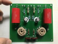
I built your Tube Output Stage today and connected it to the AD1862. I'm happy to hear that I prefer the sound over the OP stage. The mid-range voice are especially attractive to me. Thank you.
Attachments

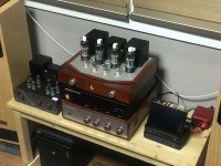
I'm curious, what is the device with a screen on the right side? Is it a Volumio streamer?I built your Tube Output Stage today and connected it to the AD1862. I'm happy to hear that I prefer the sound over the OP stage. The mid-range voice are especially attractive to me. Thank you.
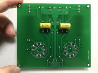
Sorry Tamra, I still wanted to ask what series are 4 blue polymer capacitors at 100 uF.Hi ewa777.
I have not compared with Wima and no measurement so I don't know what is better build. Only I can say this is really good DAC in my system.
I used Panasonic echu because from good reviews and cheaper than Wima here.
It was difficult to solder and I am not sure I could soldered right
Polystyrene cap have better reviews.I found copper film polystyrene cap but I am thinking that probably echu was good choice for more close to PCB low noise or inductance.
4.7uf pml cap I choose without comparison.
Polymer hybrid cap 47uf was better than nichicon gold tune or nippon-chemicon kzh.
But 100uf at output,I didn't like polymer so I choose Nippon-chemicon.
Thank you.
I started to solder the parts... Please look at shift registers - are they properly soldered? This is my first chips and smd's😀
I have a trouble with Dale resistor - he is too big for place on board - what should I do?
Unfortunately I can't build PSU-2. I will be look an another PSU (my friend got one). Do I must solder 2R2 or just jumpers (J1-J13)?
I also buy Amanero and need the transformer (I guess I'll order from ali R-Core 12V). The last parts will be soldered on next week!
Attachments
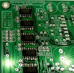
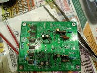
@sworder84 SMD chips are looking good 😉
... just bend the legs on Dale resistor
Yes, you can solder 2R2, you won't lose anything 🙂
... just bend the legs on Dale resistor
Yes, you can solder 2R2, you won't lose anything 🙂
@miro1360 back side have only two smd's and not difficult to solder them. I'm glad about 74HCT's 🙂
Dale have a big body and I put down him but is there a small distance between board and resistor. I hope is ok too!
Mouser is not send to me is one thing - 113316 (dip 16 for chips 1862). I will buy them a local shop.
Dale have a big body and I put down him but is there a small distance between board and resistor. I hope is ok too!
Mouser is not send to me is one thing - 113316 (dip 16 for chips 1862). I will buy them a local shop.
@sworder84 The small distance between board and resistor is ok.
Preferably buy the socket with golden contacts 🙂
Preferably buy the socket with golden contacts 🙂
Thanks !!!Nice work Soonmo!
You whipped up a pcb for the tube output stage quickly 👍.
DIY streamer. It is HP Thin Client t420. I installed debian linux, MPD, and upmpdcli, etc.I'm curious, what is the device with a screen on the right side? Is it a Volumio streamer?
Hi Soonmo,I built your Tube Output Stage today and connected it to the AD1862. I'm happy to hear that I prefer the sound over the OP stage. The mid-range voice are especially attractive to me. Thank you.
which tube are using? where can purchase this pcb?
I'm happy that you enjoy it 🙂I built your Tube Output Stage today and connected it to the AD1862. I'm happy to hear that I prefer the sound over the OP stage. The mid-range voice are especially attractive to me. Thank you.
What is your B+ voltage?
According to my experience string instruments are sounding so realistic. Generally the music is more "live" for me.
You can try another capacitors at the output. This is a really basic circuit the result is highly depend on the components. You can fine tune the sound according your taste.
I'm happy that you enjoy it 🙂
What is your B+ voltage?
According to my experience string instruments are sounding so realistic. Generally the music is more "live" for me.
You can try another capacitors at the output. This is a really basic circuit the result is highly depend on the components. You can fine tune the sound according your taste.
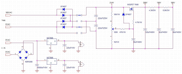
I'm using FET ripple filer circuit. B+ is 205 VDC now, it can be adjusted from 180 ~ 22?
K voltage is 2.53 VDC. I'll try another caps at the output.
Attachments
I'm using 6n23p. I ordered from jlcpcb. Circuit and gerber files are from @gaszto.Hi Soonmo,
which tube are using? where can purchase this pcb?
- Home
- Source & Line
- Digital Line Level
- DAC AD1862: Almost THT, I2S input, NOS, R-2R