A very easy, low damage way to access the current outputs is to use a dummy opamp socket with wires soldered into pins 2 and 3. The wires can then feed whatever output stage you want to try. I have been using this setup for all my experiments (which have been many lol!) and it works very well.
I've only tried 2 valve stages so far - one is a 3a5 DHT stage (lots of work, but great sound). The second is a 6n2 stage from aliexpress (look up 6n2 srpp on aliexpress) which is actually very good, especially with better 6n2 valves. This has a more forward sound than the 3a5. Its also a hell of a lot cheaper, very easy to build and no hum/RF issues that you might have with a DHT stage.
I've only tried 2 valve stages so far - one is a 3a5 DHT stage (lots of work, but great sound). The second is a 6n2 stage from aliexpress (look up 6n2 srpp on aliexpress) which is actually very good, especially with better 6n2 valves. This has a more forward sound than the 3a5. Its also a hell of a lot cheaper, very easy to build and no hum/RF issues that you might have with a DHT stage.
Woodturner-fran that dip connector solution is exactly how I lead the i out current to tubes.
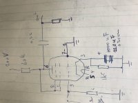
I made a simple ef86 as triode connected single tube stage. First want to try 200 ohm iv resistor, but with only 1 ma trough tube I search some other bias values
Output cap is now 2,2 uF ERO mkc with philips KS bypass cap
I made a simple ef86 as triode connected single tube stage. First want to try 200 ohm iv resistor, but with only 1 ma trough tube I search some other bias values
Output cap is now 2,2 uF ERO mkc with philips KS bypass cap
Attachments
Last edited:
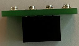
Guys, I created a little board for myself to leverage U.FL connections between Miro's boards (for existing builds) and an I2S source with normal header connections, in my case PPY's re-clocker for Beaglebone boards.
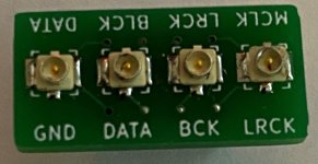
I added labels to the different connections so that it can be oriented to line up with the respective board (Miro or PPY). However, it's a straight through connection to the bottom header, so it can be used in any orientation.
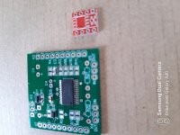
I'm sharing the Gerber files if anyone else every needs a similar solution. This is my first attempt at designing a PCB, so I'm sure I did everything wrong. 😱 The good news is that it does work! 😀
Mouser BOM
x 4 : u.FL - 798-U.FL-R-SMT-110
x 1 : Header - 710-61030821821
I added labels to the different connections so that it can be oriented to line up with the respective board (Miro or PPY). However, it's a straight through connection to the bottom header, so it can be used in any orientation.
I'm sharing the Gerber files if anyone else every needs a similar solution. This is my first attempt at designing a PCB, so I'm sure I did everything wrong. 😱 The good news is that it does work! 😀
Mouser BOM
x 4 : u.FL - 798-U.FL-R-SMT-110
x 1 : Header - 710-61030821821
Attachments


Bravo 🙂
I know also IanCanada made a UFL adaptor for the I2S output of a RaspBerry Pi header for the one using such sources (with a reclocker hat, please 😉 )
I know also IanCanada made a UFL adaptor for the I2S output of a RaspBerry Pi header for the one using such sources (with a reclocker hat, please 😉 )
Woodturner-fran that dip connector solution is exactly how I lead the i out current to tubes.
I made a simple ef86 as triode connected single tube stage. First want to try 200 ohm iv resistor, but with only 1 ma trough tube I search some other bias values
Output cap is now 2,2 uF ERO mkc with philips KS bypass cap
I have some of those KS from Philips... a gem, imho 😎 ! 33 nF.... on hands for the biggest ! Many good enough for a DC blocking output cap with a 47 K ohms input Pre !
A very easy, low damage way to access the current outputs is to use a dummy opamp socket with wires soldered into pins 2 and 3. The wires can then feed whatever output stage you want to try. I have been using this setup for all my experiments (which have been many lol!) and it works very well.
I've only tried 2 valve stages so far - one is a 3a5 DHT stage (lots of work, but great sound). The second is a 6n2 stage from aliexpress (look up 6n2 srpp on aliexpress) which is actually very good, especially with better 6n2 valves. This has a more forward sound than the 3a5. Its also a hell of a lot cheaper, very easy to build and no hum/RF issues that you might have with a DHT stage.
Thank you. This is what I wanted to know. Do I need to put a resistor for AD1862 ? Do you have any pictures please?
I intend to use a 6CG7
47pf capacitor for I/V resistor seems too low. for 1.4k i/v resistor cutoff will be 2.4mhz.
Am I missing something?
Am I missing something?
Last edited:
Thank you. This is what I wanted to know. Do I need to put a resistor for AD1862 ? Do you have any pictures please?
I intend to use a 6CG7
Mu is too low
 imho, same problem than Tubee = more difficult with the too big I/V R value = distorsion.... that little dac chip has only 2ma compliance if my memory serves me well which is not perhaps 🙄 ! (Or at least use drop the I/V R value and use more gain with the pre after ?)
If I may, you should cop an already established design (I gave a name above in a post) or simply go the route of the op amp which is less dangerous than playing with HV if not confortable at reading a datasheet 😱. You may have a better result with the LM opamp than going tube route that way, imho... way safer for the health and sound ! Of course YMMV, but someone had to alarm you on that risks. (no offense).
Safer to follow what Fran already experienced if you want to follow the tube route or read the article of the guy I talked about (which means working with higher Mu).
just my 2 cents.
Last edited:
just don't use it !
Diyiggy, In this case, it will cause lots of hf at the output? (out of band noise!)
every technote suggests there must be a cap paralel to i/v resistor for hf cutoff and it should be calculated for target hf rolloff value.
I'm trying to understand why some designs does not use it or use very low value while other designs uses much much higher values for more or less same target fq.
For an example; Pedja uses 1n for 1.5k i/v resistor.
It"s because of the type of OpAmp - some OpAmps have the current feedback and this capacitor will make them to "whisle")). AD811 for example..
I'd like to try Pedja Rogic's discrete schematic.
But there is a problem with transistor matching and thermostatis...
On one photo pedja's schematic, on the second - LH0002.
I must add only two transistors and four resistors 1K )))


But there is a problem with transistor matching and thermostatis...
On one photo pedja's schematic, on the second - LH0002.
I must add only two transistors and four resistors 1K )))
Hi Vunce,
How please one has to populate the adaptator C1 value? According the oap datashhet ? Do you populate the top R two aeras ? How much R please ? With Fca acrylic cap it must change the game on the right side vs x7r I don,t like.
Here your board near Meldano member 's Muse volume control board...rhe littliest smd I soldered...yestzrday during the french national day firework...just in case of scream, yell, nervous breakdown to hide the spl volume of your servitor....was ok with flux.
@ Aleev Edit...have to show you later Rogic mirror on the painkiller member ad1862...To package are so close I surmise there is a thermal coupling and at the end each transistor must have perhaps the same temperature...
Is it the problem you highlight ?
Attachments
Last edited:
Aleev, I found an old picture...look how the diamond Rogic arrengement made by Painkiller member is compact 🙂...4 layers board.
@ Miro...as I asked to Painkiller a SGSGSG I2S arrengement...I successed to hack the througholes with uf-l pads in between...lol. Notice the good Rhopoint at the outputt I/V...just 1k...the pre after is doing the job enough 🙂.
@ Miro...as I asked to Painkiller a SGSGSG I2S arrengement...I successed to hack the througholes with uf-l pads in between...lol. Notice the good Rhopoint at the outputt I/V...just 1k...the pre after is doing the job enough 🙂.
Attachments
Hi Iggy,
100nF 0603 for the bypass cap. The two resistor dividers for the unused opamp half are 47K5 0603's. The value isn't critical, as long as they're the same and 10K or more.
Cheers!
100nF 0603 for the bypass cap. The two resistor dividers for the unused opamp half are 47K5 0603's. The value isn't critical, as long as they're the same and 10K or more.
Cheers!
Lol, Diy... yes... I have a video of the wife going to the post office for picking myreceived shipments if you want 😀 ? (I answer in advance to the next remark : yes dressed on the video, not naked  )... I think the bikini is diy... from my side, just the video is...
Did you see I never show a populated pcb or not too much ?? I prefer naked toys, lol ! suited pcbs in a nice box is too much porn for me, find it digusting... maybe one day will show one terminatored !
Btw , have you purchased your Aya5pcb at Audial ?Hurry up, the operation is finishing yet and you must have a TDA1541A dac as well (there is DIY things to solder on the pcb of course... and uf-l... I asked)
)... I think the bikini is diy... from my side, just the video is...Did you see I never show a populated pcb or not too much ?? I prefer naked toys, lol ! suited pcbs in a nice box is too much porn for me, find it digusting... maybe one day will show one terminatored !
Btw , have you purchased your Aya5pcb at Audial ?Hurry up, the operation is finishing yet and you must have a TDA1541A dac as well (there is DIY things to solder on the pcb of course... and uf-l... I asked)
Last edited:
- Home
- Source & Line
- Digital Line Level
- DAC AD1862: Almost THT, I2S input, NOS, R-2R