There is something intriguing me about your shift register functionality I would like to consult you about.

First you are delaying the data by 16bits, why?
The I₂S sends the two channels consecutively indicating by LRCK which channel is concerned. Normally the clock of each DAC is activated when it is its data is pouring, or else it waits until the other channel has finished swallowing what it concerns. If the data is longer than its capacity the extra received bits are discarded.
Your system delays the LD by 32bits with respect to RD. This can work only if the I₂S is pouring 32bit/channel data. If it is 16/channel, than the left will load that of the right channel's preceding one isn't it, so no left channel. What if it is receiving 24bits?
Last edited:
>>First you are delaying the data by 16bits, why?
Not 16, but 11.
>>If the data is longer than its capacity the extra received bits are discarded.
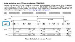
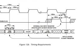
Exactly that is happening. Standard I2S word length is 64-Bit (for both channels as 32+32, MSB first) selecting between them by LRCK (0, 1). LRCK is 1-Bit delayed (data is almost left justified). AD1862 is 20-Bit also MSB first but right justified. Therefore it is enough to create a 11-Bit delay for the data (32-11-1=20) ... where -1 aligns LRCK because LRCK comes delayed to the data (to the whole 64b word/sample). The rest data are discarted. When all data is clocked into DAC, a low going LRCK updates the DAC output. In case of this DAC both channels are played simultaneously because 4 additional shift registers works as a 32-Bit buffer for one channel.
>>What if it is receiving 24bits?
20 most significant bits are played, 4 lsb are discarted.
Not 16, but 11.
>>If the data is longer than its capacity the extra received bits are discarded.
Exactly that is happening. Standard I2S word length is 64-Bit (for both channels as 32+32, MSB first) selecting between them by LRCK (0, 1). LRCK is 1-Bit delayed (data is almost left justified). AD1862 is 20-Bit also MSB first but right justified. Therefore it is enough to create a 11-Bit delay for the data (32-11-1=20) ... where -1 aligns LRCK because LRCK comes delayed to the data (to the whole 64b word/sample). The rest data are discarted. When all data is clocked into DAC, a low going LRCK updates the DAC output. In case of this DAC both channels are played simultaneously because 4 additional shift registers works as a 32-Bit buffer for one channel.
>>What if it is receiving 24bits?
20 most significant bits are played, 4 lsb are discarted.
Last edited:
If the I₂S has 2×16bit data, delaying 32bit you come back to the same channel. There is no standard I₂S 2×32bit. for 16bit, it is 2×16, for 24bit ,it is 2×24 and only for 32bit it becomes 2×32. If it is 24bit, than the left channel gets data of some of right and some of left, no?
Last edited:
>>for 16bit, it is 2×16, for 24bit ,it is 2×24 and only for 32bit it becomes 2×32
Not quite like that.
For the most common I2S devices the bitclock is configured as 64fs (2x32 is produced even for 2x16bit data, the rest bits are 0) ... some devices have tool to reconfigure it as 128fs etc. (XMOS, CM6631A) ... the RPI is as 64fs for most frequencies (except for 192kHz and higher it is as 48fs - that is why RPI can't play 192kHz on this DAC).
Exists a small and super cheap asynchronous USB-I2S chip from silabs which comes as 48fs (CP2615) and it is 48fs - so this one will not work here 😀 ... but the shift registers can be reconfigured for 48fs as a new design or just separated PCB for shift registers.
Even the PCM2706/7 is 64fs, ... WM8805 and AK4118 is 64fs (SPDIF to I2S)
Attachments
Last edited:
You are wrong with I₂S definition.
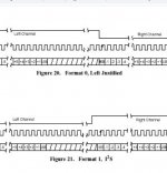
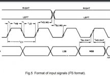
Concerning the Left/right justified, here is the timing diagram.

It looks like the AD1862 is compatible with I₂S timing.

Concerning the Left/right justified, here is the timing diagram.
It looks like the AD1862 is compatible with I₂S timing.
Attachments

Last edited:
Clock rate and word length are two different things. You can very well use 8 bit with 1Ghz, or N×fs and have 10khz 64bit.
I insist, the word length of I₂S is variable according the number of bits it carries.
I insist, the word length of I₂S is variable according the number of bits it carries.
>>I insist, the word length of I₂S is variable according the number of bits it carries.
It could be variable but is not so much variable 😀
Consider PCM2706 as USB-I2S. It outputs 64-bit word which contains 2x16-bit (all extra bits are 0). ... As I understood your definition, the word has to be 32-bit, but it isn't and is 64. With I2S there are some common implementations and the most common one is where there are 32 bits for each channel of data (2x32=64).
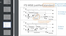
Maybe this can help you:
64-bit word considered as standard even on courses
The reality is that most USB-I2S devices are configured as 64-bit and that is what this DAC accepts 😉
It could be variable but is not so much variable 😀
Consider PCM2706 as USB-I2S. It outputs 64-bit word which contains 2x16-bit (all extra bits are 0). ... As I understood your definition, the word has to be 32-bit, but it isn't and is 64. With I2S there are some common implementations and the most common one is where there are 32 bits for each channel of data (2x32=64).
Maybe this can help you:
64-bit word considered as standard even on courses
The reality is that most USB-I2S devices are configured as 64-bit and that is what this DAC accepts 😉
Attachments
Last edited:
>>They are identical, you don't need any shift register.
Again wrong 😀
The TDA1543 is stereo and accepts I2S Phillips standard data with any bit length (internal digital circuitry can distinguish it).
AD1862 is mono and accepts I2S with constant bit length (20-Bit) and that is where the shift registers come in the play.
Seems like this is something new for you 🙂

I certainly appreciate you sharing this AD1862 project with us, Miro. It’s been a joy to work with. The only “bought” items are the parts to fill it 😀
I agree, miros shared a good design for free.. and that is all about diy!I certainly appreciate you sharing this AD1862 project with us, Miro. It’s been a joy to work with. The only “bought” items are the parts to fill it 😀
Not much people doing that on this forum.
I see some talented mind guys... telling half of the story in many posts... and doing bussiness on the backside, but this is off topic and is another story..

- Home
- Source & Line
- Digital Line Level
- DAC AD1862: Almost THT, I2S input, NOS, R-2R