Miro,AD1862 Stop-Clock
Corrected PCB, hopefully without mistake 🤐 (the mistake was in the LRCK, for the left channel it must be inverted).
It incorporates the Stop-Clock system. What does that mean? Simply: The BCK (clock) is off while no data are present for DAC chip.
Only 4 digital chips are on the PCB. The simplest stop-clock as it gets from my "studio" 🤩 The only drawback from this simplicity may be a channel shift by 10ns (because I left out the 32-bit buffer).
(I shifted channels in audacity by 100ns (10x worse scenario) and I hear no difference, so this shift should not cause any problem.)
Another "major" change is in the ground plane on the PCB. I divided the GND plane for digital and analog with thick cut lines. This helps eliminate potential digital interference and can have another positive impact on the sound 🤩
BOM example: https://www.mouser.com/ProjectManager/ProjectDetail.aspx?AccessID=c547c05bf3
note: I/V OpAmp in BOM is LM7171, you can buy another one
The PCB is not tested ... (maybe even more coasters to the collection LOOOL 🤣)
To achieve stopped clock operation can't we add an AND gate to the original logic from post #1 with BCLK on one input, LRCLK on the other - the output is the DAC CLK that turns off when LRCLK goes low?
What am I missing?
@lasercut
If you dig deeper in the forum, you can find the stop-clock version 🙂
Note, that pin 8 on I2S data header is unhappily disconnected and if used, you need to connect it with pin 7 (or use pin 7).
For even better stop-clock you can use this https://electrodac.blogspot.com/p/i2s-to-pcm-dac-converter-tutorial-cpld.html
Attachments
-
diyAudio_AD1862_DAC_v2.1_Stop-Clock_2022-05-28.zip657.1 KB · Views: 102
-
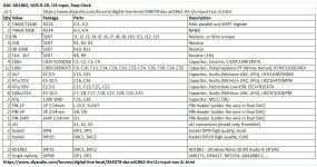 diyAudio_AD1862_DAC_v2.1_Stop-Clock_BOM.jpg209.1 KB · Views: 198
 -
 diyAudio_AD1862_DAC_v2.1_Stop-Clock_parts.jpg220.8 KB · Views: 182
 -
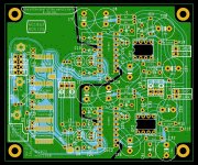 diyAudio_AD1862_DAC_v2.1_Stop-Clock_PCB.jpg411.3 KB · Views: 227
 -
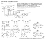 diyAudio_AD1862_DAC_v2.1_Stop-Clock_Schematic.jpg464.5 KB · Views: 226

Forgive me if this is answered elsewhere in this thread as I did not find with a search.
I have acquired a couple AD1862 chips and want to build a DAC that exceeds the performance of my current TDA1541a DIY DAC.
The circuit on this thread looks great and I intend to try it out with the stopped clock and, likely, a tube gain circuit on the analog side.
My current question is about power supply.
I have a good supply of 2.4V LTO batteries. Since 2.4 x 5 = 12v I was thinking of finding appropriate balancing boards (perhaps could repurpose some intended for 2.7 V ultracapacitors) and creating 12v power supplies with floating charging ( which I've discovered these batteries tolerate well) that disconnects via relay with music playing.
Does anyone have experience using these LTO batteries in an AD1862 (or similar) DAC?
Any advice?
Thank you
Chris
You can't exceed the king of multibit dacs 😁 Only with the same chip with SOTA layout 😇I have acquired a couple AD1862 chips and want to build a DAC that exceeds the performance of my current TDA1541a DIY DAC.
Honestly, can't tell you if it will be better or not, it really is up to your taste.
Now the question at hand, badly implemented and dubious quality batteries sound worse than proper newer series regulator. Let alone shunt supply. For tda1541a good battery supply or shunt, sound good supplying 5V. Super caps should be even better. For ad1862 i can't tell for sure, but well implemented battery pack should sound good.
Thank you Brijac. Yes, I am using LTO batteries and supercapacitors on the -15v of the TDA1541a DAC. And Studer 900 and supercaps on the +/- 5v supplies. I use Ian Canada's FifoPi and PCM board on the front end and a DIY jfet IV.
It sounds pretty good.
And AD1865 DAC I built previously sounds close - not quite as analog - so I am AD1862 curious.
Figuring out some really good +/- 12v supplies is at the top of the to-do list at the moment.
It sounds pretty good.
And AD1865 DAC I built previously sounds close - not quite as analog - so I am AD1862 curious.
Figuring out some really good +/- 12v supplies is at the top of the to-do list at the moment.
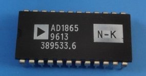
Even the AD 1865 does not sound the same in all versions. The best is AD 1865 N-K of the first series with smaller font .
.png")
they start with 96 number or 99 - this 04 above is some special series for Audio Note (UK)
the problem is that they are not available to buy.😎
they start with 96 number or 99 - this 04 above is some special series for Audio Note (UK)
the problem is that they are not available to buy.😎
I have started to build the DAC and also headphone amplifier / preamp. I thought the headphone amplifier would adjust volume of headphones and amplifier, but now I noticed the other way is just straight though. Maybe if I cut traces etc it can be used like I want or are there any downsides to it?
Between 1999 and 2005 I bought AD1865 and a few others directly from AD distributors in singapore purchased the DIP version and then the SOIC version primarily NKs. I have made a number of DACs around this chip both Iout and Vout, contrary to the popular belief I have always found them to be among the top 3 (not including AD1955). When I built miro's DAC around AD1865, AD1862 and TDA1541 I somehow found that AD1865 was not up to the mark, till the time I realized that OPAMPs are being powered by 5 volt supply, recently fixed it to 14.5 volts and now I can say it is definitely up to par with any other R2R chip, when coupled with AD8610 or Bursons or OPA627 TO CAN version it is one helluva DAC.Even the AD 1865 does not sound the same in all versions. The best is AD 1865 N-K of the first series with smaller font .
View attachment 1290466
they start with 96 number or 99 - this 04 above is some special series for Audio Note (UK)
the problem is that they are not available to buy.😎
Just to test things out a year and change back I purchased another of these from a chinese seller at ebay and NK version, and trust me it sounds horrible.
I also took one of the Chinese ones to try, the one with the small white letters. Admittedly, this one is a bit older, from 1996 and yours is from 2003/5. It sounds very good vith Burson V6 Classic (naked), like all the others I've bought. And I've made quite a few, so I have something to compare with (DDDAC PCM1794/Miro PCM63/ Miro AD1862).
If you offer a good price, I would take the risk of buying a pair of AD1865N-K from you. 😎
If you offer a good price, I would take the risk of buying a pair of AD1865N-K from you. 😎
Attachments
Anything with an external opamp sounds too harsh to me. That's why I'm on the Pavouk version that uses an internal opamp.
we concluded that a tube is always better than an average op amp.
Capacitive connection between 1702 and the tube cathode? So, two extra coupling caps compared to the opamp i/v and still better, right?

It would be better to add 2 additional relays on the output with which you can switch between headphones and other devices 🤔I have started to build the DAC and also headphone amplifier / preamp. I thought the headphone amplifier would adjust volume of headphones and amplifier, but now I noticed the other way is just straight though. Maybe if I cut traces etc it can be used like I want or are there any downsides to it?
You can do that with 2 DPDT relays and one switch and a lot of wiring 🤣
Attachments
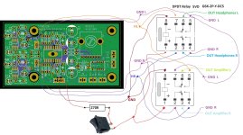
Thanks! I will do it like that! I'm still waiting some parts for the dac, but at least psu1 and headphone amp are alive 😊It would be better to add 2 additional relays on the output with which you can switch between headphones and other devices 🤔
You can do that with 2 DPDT relays and one switch and a lot of wiring 🤣
It is very sensitive, small DC offset is amplified (R2 R3) ... maybe you will need edit these values a bit, because I experienced triggering in some recordings (where a lot of noise is present (like strong wind)). With default values it should be 130mV 🙂@miro1360 I will add to your DC protection a 555 timer for few sec. delay when switching on, I plan to use it for the headphone amplifier. At what mV DC does the protection turn on?
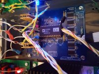
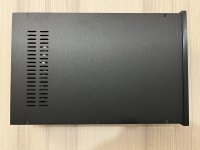
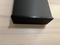
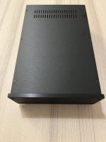
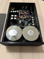
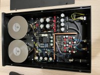
Almost final build. I will change signal cables for the RCA OUT and 230V mains cable. I am planning to implement Power Button on the front panel as well. But so far so good. Many thanks Miro for your great design and your support. And since on the current PCB it is a little bit complicated to install Burson Audio OpAmps, I am building another PCB, which will have caps on the bottom side. And without shift registers, to fully utilize JLSound Boards. 🙂 Comparing to ADI-2 DAC FS, no hum from the speakers is audible at idle mode, which is great. 😊 The sound itself is really amazing. But I will need more time for listening, and it will change with Burson anyway 😀
Attachments
-
 IMG_4631.JPG506 KB · Views: 154
 -
 IMG_4632.JPG385.3 KB · Views: 134
 -
 IMG_4633.JPG427.8 KB · Views: 132
 -
 IMG_4634.JPG423.9 KB · Views: 123
 -
 IMG_4635.JPG479.3 KB · Views: 112
 -
 IMG_4636.JPG442.6 KB · Views: 168
 -
 IMG_4637.JPG455 KB · Views: 233
 -
 IMG_4638.JPG564.6 KB · Views: 237
 -
 IMG_4639.jpg502.1 KB · Views: 228
Very nice build amadeus, i like it a lot🙂 Very clean. Wish Ljuben would make black version of JLS board 🙂
I wish JLS board would be black as well. And of course Happy Easter Holidays. Христос Воскресе 🙂
🙂
🙂
- Home
- Source & Line
- Digital Line Level
- DAC AD1862: Almost THT, I2S input, NOS, R-2R