No change at all.
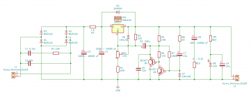
Ok. I noticed that Elvee's LTSpice schematic has a low-ESR cap at output (C5, 50m series resistance). I used a cap with higher series resistance (800m) in my simulations which seems to be the cause for oscillations. So at least based on Spice simulations it appears dienoiser requires a low-ESR cap at output.
Hmm, I have 100 uF/220 mΩ cap at output in the real dienoiser circuit and it does not oscillate, even without 22 nF compensation capacitor. It was many times reiterated in this long thread that very low ESR capacitor at LM317 output can introduce oscillation. In LTspice is the opposite. 😕
There was one case where adding 1 uF ceramic capacitor at output, in parallel with electrolytic cap, made denoiser (single transistor) circuit to oscillate.
There was one case where adding 1 uF ceramic capacitor at output, in parallel with electrolytic cap, made denoiser (single transistor) circuit to oscillate.
Like I said before my miniature dienoiser oscillates with 100u/600mohm. I'll test it with a low-ESR cap tomorrow. However I do not particularly like circuits that are on the verge of oscillations. Especially as an add-on since changing to a low-ESR output cap may not be feasible in an existing hardware.
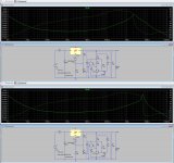
Yes (with some caveats): it is why I recommended Kumori to probe the adj. pin when he had oscillation issues.Only that if the control system is unstable, and if Nyquist oscillation is observed on node "AAA", we also expect to observe it on BBB, CCC, DDD, and EEE too.
Among them, I expect the greatest amplitude at BBB and EEE. Probing them ought to give the easiest-to-see oscillatory waveforms. Plotting what's easy to see, feels like a useful decision.
_
The caveat is that the oscillation is then supposed to be mostly related to the main GNFB loop, which is probably not the case for a CFP combined with the inherent slowness of the 317.
It then becomes mainly a local stability issue, exacerbated by external phaseshifts.
As I said earlier, it points to a local issue, and indeed shortening the timestep to very small values (even 1ns or less) can reveal something.The oscillation amplitude is greatest at the junction of the Sziklai transistors (i.e. DDD in your schematic). Here I also shortened the timestep which makes the oscillations appear sooner.
There are many other factors to take into account: the solver chosen in LTspice, the various parameters (Gmin, abstol,...) etc
As for LTspice, see above: unless all the options are forced in the .asc, you cannot be sure that "your" LTspice is the same as the other person's one.Now, one crucial question: why I can’t get oscillations on the same model at any spot (A,B,C,D,E)?
As I can’t induce them on real circuit as well. Isn’t this just LTspice quirk?
Try really short timesteps.
In the real circuit, I wasn't able to observe oscillation either, but I only made a breadboard test.
Diego's original sim (not LTspice) looked stable without any comp capacitor, but in reality I had to add one to get it stable
I also do not like such circuits, but the Die-noiser adds another layer of performance (~20dB) to the regular denoiser, and as we all know, there are no free lunches in engineering.Like I said before my miniature dienoiser oscillates with 100u/600mohm. I'll test it with a low-ESR cap tomorrow. However I do not particularly like circuits that are on the verge of oscillations. Especially as an add-on since changing to a low-ESR output cap may not be feasible in an existing hardware.
The no-noiser has similar performances, and is similarly touchy (but is not intended for retrofitting).
The basic denoiser is much more tolerant, and has been explored and tested for many cases and situations. It does not tolerate insane output caps combinations or the lack of of a proper input bypass, but that is also the case of many non-augmented regulators.
I am not completely sure, but FKP caps are tuning capacitors, meaning their self inductance does not matter very much (up to a point).
Unlike extended foil types, they have one or two connection points to the foil, and this means that their HF bypassing capability is limited.
A ceramic disc or MLCC is quite sufficient for this job, and doesn't have this kind of issue.
The circuit might be stable with no cap at all, but I do not recommend it as a final solution: there will be some HF peak in the FR
Some news from my oscillation problem:
Apparently the problem wasn‘t the compensation cap, but the output cap. I used Panasonic FR types (100uf, 100V, ESR 0,083 Ohm at 100kHZ). It seems this ESR is too low. After adding 0,33Ohm in series to ground, the positive regulator behaved stable with any cap I used for bypass (10nF and 20nF FKP, 10nF polystyrene and 100uF ceramic). Before all caps caused oscillation, also with added 27R in series.
The negative reg shows some oscillation without the compensation cap and without series R at the output cap. I will check that tomorrow, but expect the same result.
Until now I didn‘t consider the Panasonic FC and FR as ultra low ESR. I choose the FR types if possible, because they have along lifetime and high temperature tolerance.... I will look for some higher ESR types...
Last edited:
Kumori,
That seems like a very important information and finding. It also seems to confirm the concerns for the output capacitor used with the 3X7 regulators, for it not to be a low ESR type.
Apparently the Dienoiser worsens this sensitivity, at the same time that it improves on the regulator specifications. It seems like the apparent price to pay for the improvements, and a very low one indeed.
It would be good if the other designers who had oscillation problems with the Dienoiser also change the output capacitor, and see if it remains stable under all conditions.
What exactly are we calling "low ESR", and since ESR is frequency-dependent, how is it to be measured?
I will look for some higher ESR types...
I use Panasonic EEUFC1J101 100 uF/63V, with rated ESR of 256 mΩ and measured one 220 mΩ.
Regulator is rock stable with it.
Important hint: Mark did put small value resistor in series with BIG output capacitor.
I use Panasonic EEUFC1J101 100 uF/63V, with rated ESR of 256 mΩ and measured one 220 mΩ.
Regulator is rock stable with it.
Important hint: Mark did put small value resistor in series with BIG output capacitor.
After consulting the datasheet, the Panasonic FC (which are all refered to as "low ESR", like the FR types) seem to have a varying ESR for different voltage ratings at 100 uF capacitance. The 63 V and 25 V types are rather (sufficently for the de-noiser) high at 0,256 Ohm and 0,350 Ohm, respectively. But the types for 35V, 50V and 100V are all below 0.18 Ohm and down to 0,117 Ohm.
Somewhere between those Panasonic datasheet values of 0,083 (in my case) and 0,220 Ohms probably is the threshold for the de-noiser.
As I suspected my miniature dienoiser does not oscillate after I changed the output cap to a lower ESR type (100uF/120mOhms). However I cannot measure the predicted 20dB improvement over denoiser. But both are already quite close to the limit of my measurement setup so it is not conclusive. I'll stick with the denoiser.
I use Panasonic EEUFC1J101 100 uF/63V, with rated ESR of 256 mΩ and measured one 220 mΩ.
Regulator is rock stable with it.
Important hint: Mark did put small value resistor in series with BIG output capacitor.
Can we say that adding a 1Ω/1W metal oxide in series with the output cap would solve any potential oscillations possible?
Can we say that adding a 1Ω/1W metal oxide in series with the output cap would solve any potential oscillations possible?
I tried the negative de-noiser today. Adding 0,33 Ohm in series to the output did not cure oscillation. I had to increase the compensation capacitance and add resistance. In the end it was stable with 20nF and 27 Ohm, and 100uF and 0,33 Ohm at the output.
The positive version was stable with and without compensation cap after adding 0,33 Ohm to the output.
The positive version was stable with and without compensation cap after adding 0,33 Ohm to the output.
That is my finding as well with 220 mΩ esr cap, so no additional resistor needed.
Now we have two points of safe ESR range: 120 mΩ (bohrok2610) to 330 mΩ.
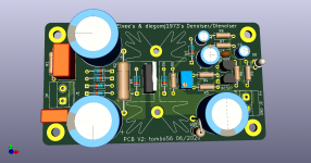
PCB V2
Here is revision of the single rail dienoiser pcb.
It now accommodates 18 mm diameter input caps. There is led indicator on the output with capacitor bypass, so it is assured that no noise will be introduced (overkill, I know). R5 resistor is moved close to output pin of LM317. Pitch for BC transistors is changed to 2,5 mm. Wonder why? I was lazy to exchange soldering tip for fine one and all pins were soldered together. That made me to replenish my curse words repertoire.
Output capacitor can be with 5 mm or 7,5 mm pitch and up to 16 mm diameter. There is position for a ESR adjusting resistor in series with output capacitor or just jumper.
If someone will build this, let me know if any help is needed with BOM list and values for specific output voltage and current.
Attachments

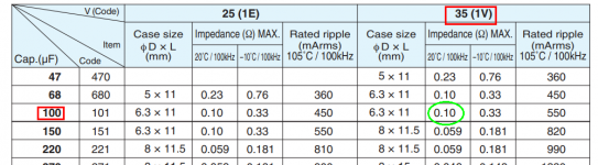
I must be missing something here. When I calculate the ESR for MY 100µF capacitor (Nichicon UHV1V101MED1TA, 100µF, 35v, tanδ = 0.11@120Hz) and using the formula:
E.S.R. = DF / 2 Pi f C, I get 1.46 Ω. That's a far cry from the coupla-hundert milliohms that everyone here is talkin'. Huh?
E.S.R. = DF / 2 Pi f C, I get 1.46 Ω. That's a far cry from the coupla-hundert milliohms that everyone here is talkin'. Huh?
... I used Panasonic FR types (100uf, 100V, ESR 0,083 Ohm at 100kHZ). It seems this ESR is too low....
I just looked at the datasheet for the Nichicon UHV1V101MED1TA and found this (green circle):
_
Attachments
- Home
- Amplifiers
- Power Supplies
- D-Noizator: a magic active noise canceller to retrofit & upgrade any 317-based VReg