You can try any NPN safely. Some will be better, some worse.Are there any other BC transistors I can safely try until I finally buy a 337 or a ZTX?
I wanted to assemble the proto pcb and try it on the regulators I already have here. Those others I would have to wait till they get here.
Even a Chinese S8050 was already much better than the 337
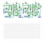
Here's the updated and corrected last version of the Dienoiser designed for assembling on a prototype pcb.
It's designed for through hole parts only, and the parts terminals are to be used as the circuit traces, twisting and soldering the wires to interconnect the parts.
Please disregard the other design I had uploaded some days ago, as it had one trace missing. Also this time, and considering some feedback from others that used the Dienoiser and seemed to have had some oscillations, I added a compensation resistor space in series with the 22n capacitor.
As soon as possible I will assemble that proto pcb here, with the parts I have, and add it to some of the regulators I also have.
As you can see, there's a vertical line in the middle, which you can use to separate the positive and negative Dienoisers, accordingly to what you need. Or if you have only positive regulators, as might be the case, repeat another positive Dienoise on the right side.
This is as easy as this project can get.
Attachments
Last edited:
You could try without the 33R
I tried the dienoiser with only 22n compensation and without compensation cap to no avail.
Sorry, a small mistake on my proto pcb.
C7 polarity is inverted. The negative side should be connected to the junction that connects to the regulator board.
C7 polarity is inverted. The negative side should be connected to the junction that connects to the regulator board.
Have you tried with a small resistor in series with the 22n cap?
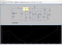
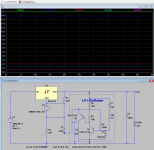
Yes, originally I had 33R in series with 22n cap. Actually it had the worst oscillations. In Spice simulations the dienoiser has a resonance at ~40MHz without compensation. Adding compensation cap just moves the resonance to a lower frequency. E.g. with 22n compensation the resonance is at ~5Mhz.
Are you running the PSRR curve to get that resonance?
If that's so, what really seems to affect the PSRR curve peak in my sim is the resistor in series with 22uF, not adding one to 22n. But I do not know what else that might be affecting?
If that's so, what really seems to affect the PSRR curve peak in my sim is the resistor in series with 22uF, not adding one to 22n. But I do not know what else that might be affecting?
Are you running the PSRR curve to get that resonance?
If that's so, what really seems to affect the PSRR curve peak in my sim is the resistor in series with 22uF, not adding one to 22n. But I do not know what else that might be affecting?
Yes, AC analysis in LTSpice.
Attachments
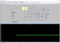
I would expect that if there's a sinewave on Vout, there's probably a bigger sinewave on the adjust pin.
I would expect that if there's a sinewave on Vout, there's probably a bigger sinewave on the adjust pin.
I'm not sure what's your point. Here is another view of the Spice transient analysis which more clearly shows the bursting into oscillation. This is taken from the "ground" leg of Cadj (C12).
Attachments
Only that if the control system is unstable, and if Nyquist oscillation is observed on node "AAA", we also expect to observe it on BBB, CCC, DDD, and EEE too.
Among them, I expect the greatest amplitude at BBB and EEE. Probing them ought to give the easiest-to-see oscillatory waveforms. Plotting what's easy to see, feels like a useful decision.
_
Among them, I expect the greatest amplitude at BBB and EEE. Probing them ought to give the easiest-to-see oscillatory waveforms. Plotting what's easy to see, feels like a useful decision.
_
Attachments
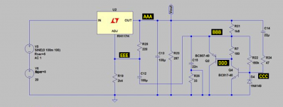
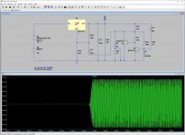
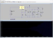
The oscillation amplitude is greatest at the junction of the Sziklai transistors (i.e. DDD in your schematic). Here I also shortened the timestep which makes the oscillations appear sooner.
Great can we then stop the oscilation with your measurents?
Kim

Why does the schematic in #896 have a 22nF capacitor in the same position where the schematic in #894 has a 10nF capacitor?
Same goes for 100uF versus 220uF
Same goes for 100uF versus 220uF
Why does the schematic in #896 have a 22nF capacitor in the same position where the schematic in #894 has a 10nF capacitor?
Same goes for 100uF versus 220uF
The tried both 10n and 22n as compensation. Both oscillated in Spice. The Cadj (100u or 220u) should have not impact on the oscillations.
Make the timestep shorter (e.g. 10u).
No change at all.
Attachments
- Home
- Amplifiers
- Power Supplies
- D-Noizator: a magic active noise canceller to retrofit & upgrade any 317-based VReg