The bevel should still go the other way. In an earlier build i got caught out by the second baffle. The cut-outs should get larger as you get deeper into the baffle.
dave
dave
Ooooo. Ouch! I think Zman may have made a critical observation. I did it myself. See post #6 in this thread. Hopefully you are one step ahead of us.
Hopefully unnecessary, but in a pinch, Bondo is your friend! I used it to reverse the bevels on my screwup.
Last edited:
So, your remedy to the situation will probably need to be similar to Alan's.
Good luck on getting it fixed, and hope you will have the speakers running soon.
Good luck on getting it fixed, and hope you will have the speakers running soon.
Thanks all. Just when I had a bit of momentum. But it is all right, except for exposing our mutual goof to the whole world here in DIYAudio
-david BTW
-david BTW
When I was in your situation, the choices looked bleak. Cut off the baffle and reverse it/make a new one was one option. Bondo was the other. I went wtih Bondo. You may need to be very careful with screwing the drivers down (epoxy, drill and tap, etc.), but you can save it with Bondo, I believe. The first approach is not much different from starting over from scratch, IMHO. Too depressing.
Another benefit of the Bondo approach is that, unless you get very clever with paint or some sort of ring to disguise the Bondo, you will need to veneer the speakers, and they will look beautiful. No stain can hide the natural ugliness of Bondo.
Another benefit of the Bondo approach is that, unless you get very clever with paint or some sort of ring to disguise the Bondo, you will need to veneer the speakers, and they will look beautiful. No stain can hide the natural ugliness of Bondo.
davebtw,
Most of us have had many goof ups throughout our DIY journey. 🙂 It's part of the process I guess.
I've drilled wrong sized holes in metal (chassis work for amp/preamps), and drawn up wrong sized cutting plans more than once. 🙂
Alan has already shared his method on how he fixed his build error; the alternative idea of a new baffle should also work:
- Treat this reversed baffle as an inner vertical brace. Make the existing chamfered holes bigger - very much possible with a router (and the right sized template), or even a jigsaw (won't look as nice, but that doesn't matter).
- Glue on a new baffle that is wide enough to cover the entire front of the speaker including the two sides
Your speaker will be 3/4" to 1" more deep (depending on the thickness of the new baffle piece), and also just a little bit heavier.
Last edited:
I feel slightly better as my helper did the gluing when I was not present. However, both boxes are the same I don't have the problem that alanhuth had of trying to match the two up.
Either take the router and re-bevel the other way, or just take a jigsaw and cut out a square (like the Elsinires do), the actual drivers sit on the 2nd baffle layer and as long as the hole in the back baffle bit is larger than the (reamed-out) cut-out on the front baffle piece. It doesn’t have to be pretty, just bigger.
dave
dave
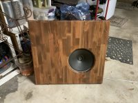
Here’s an example of an almost Bondo save on some OB baffles I made for vintage Zenith drivers. I was using the router rule of thumb that you should always go counter-clockwise. Except on an inside cut, in which case you go clockwise. So my router took off on it’s own and cut a 1 inch gouge into the rounded opening. Bondo’d it up and then faked the butcher board look with some paint and you don’t notice it unless you are looking for it.
Attachments

Yes exactly, just bigger behind. I had thought of the square cut out as well. We will tackle that on Monday.Either take the router and re-bevel the other way, or just take a jigsaw and cut out a square (like the Elsinires do), the actual drivers sit on the 2nd baffle layer and as long as the hole in the back baffle bit is larger than the (reamed-out) cut-out on the front baffle piece. It doesn’t have to be pretty, just bigger.
dave
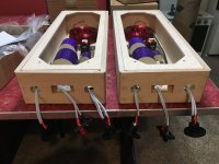
While my woodworking neighbor is continuing the assembly of the boxes I wired up the crossovers in the base units today.
On our messed up interior baffle we are using a professional grade wood epoxy to smooth out the goofs. My woodworking is a professional and this is an epoxy that he uses all the time and really likes, and it will provide the necessary backing for the mounting screws especially of the A10pen.
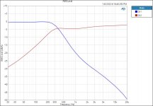
I decided to measure the crossovers today just to verify that I wired them up correctly. I put a 4 ohm resistive non-inductive precision load on the low frequency output and an 8 ohm precision load on the high frequency output. I know this is not precisely the impedance the a10Pen presents which the data sheet places at 6 ohms. And of course the real drivers present a complex impedance that varies with frequency. I then drove the input of the crossover from a 120 Watt amplifier at 2VRMS (equivalent to 1 Watt into 4 ohms). I then plotted both outputs of the crossover on the same graph with 0 dBA equal to the same 2VRMS level.
Both crossovers appear to be working correctly and the frequency response curves are dead on top of each other when plotted. Here is what they look like. I am now ready for final finishing the cabinets and mounting the drivers. Can't wait. It has been years coming. But it makes for a good project while quarantining from COVID. Measured distortion is more than 100 dB down below 2 watts so I have no fears (not shown here).
-david BTW
On our messed up interior baffle we are using a professional grade wood epoxy to smooth out the goofs. My woodworking is a professional and this is an epoxy that he uses all the time and really likes, and it will provide the necessary backing for the mounting screws especially of the A10pen.
I decided to measure the crossovers today just to verify that I wired them up correctly. I put a 4 ohm resistive non-inductive precision load on the low frequency output and an 8 ohm precision load on the high frequency output. I know this is not precisely the impedance the a10Pen presents which the data sheet places at 6 ohms. And of course the real drivers present a complex impedance that varies with frequency. I then drove the input of the crossover from a 120 Watt amplifier at 2VRMS (equivalent to 1 Watt into 4 ohms). I then plotted both outputs of the crossover on the same graph with 0 dBA equal to the same 2VRMS level.
Both crossovers appear to be working correctly and the frequency response curves are dead on top of each other when plotted. Here is what they look like. I am now ready for final finishing the cabinets and mounting the drivers. Can't wait. It has been years coming. But it makes for a good project while quarantining from COVID. Measured distortion is more than 100 dB down below 2 watts so I have no fears (not shown here).
-david BTW
Attachments

davebtw,
Is your woodworking neighbor going to chamfer / bevel the insides of the driver mounting holes?
Is your woodworking neighbor going to chamfer / bevel the insides of the driver mounting holes?
Yes I did get a pair from you Dave. It was quite a while ago now. They have the darker gray cones.Did i sell you a pair of those? Alan also has a pair.
dave
Yes we do have a plan for a bevel. We will see how it turns out. It will be a little of a compromise and not as nice as the original flat pack was, but it is either that or start over on the boxes.
- Home
- Loudspeakers
- Multi-Way
- Curt Campbell's Halcyon build thread