ostripper said:I haven't tried the "jam" mirror yet .. no more SMD's left.
I like to see the sim verifying what I hear..🙂 could anybody
SIM a unbalanced degeneration on the LTP.(auto balance effect)
The wide offset range is most curious..
Line up .. try hooking collector of U1 to other rail instead of ground
(use very high Vceo tranny) w/ 2.2k res. cancels ripple (PSRR)
2 birds w/ one stone..
PS .. I,m "relistening" to floyd now,never heard it like this on any
audio I bought in a store. thanks DIYaudio.. 🙂 🙂
OS
U1 to other rail.
Yes, but for my test is no other rail 😀
But if you study one of my amplifiers, you see practically never bias something from GROUND in a dual supply design.
Keeps ground clean and takes advantage of high CE-voltage for transistors.
Say you have a 2 transistor VAS, in darlington config.
It is tempting to put the 'driver' collector to GND.
But I would not do this, if could be avoided.
Same if I would power one LED reference.
I prefer to connect the resistor to other supply rail , to bias the current source reference voltage.
Mr.Pass,
........................I believe you may have discovered the non-pharmicutical version of Viagra! 😀
Jam
........................I believe you may have discovered the non-pharmicutical version of Viagra! 😀
Jam
I have to say that I am proud to have a mirror named after me.
The mirror in your image with all the "gothic lettering'..
like "ye olde Medieval mirror"
😀
by sandyK : I hope that the wooden case doesn't have any screws ? It must be glued together
I just don't want the little ones to get shocked and want to give the amp a months test. This is my first "listening amp' besides
BJT sub amps and chipamps. I will line 'woody" with aluminum
roof flashing as a precaution.
OS

What about differential VAS? Or differential folded cascode "VAS"?
Instead of using current mirror loaded LTP, the differential VAS will bring balance in LTP transistors.
Instead of using current mirror loaded LTP, the differential VAS will bring balance in LTP transistors.
CM Discussion
"What about differential VAS? Or differential folded cascode "VAS"?
Instead of using current mirror loaded LTP, the differential VAS will bring balance in LTP transistors."
roender
The balance will be much better, but I found that due to thermal drift considerations in the VAS, the same close balance improved performance with this topology also. Obviously, different methods were needed to keep the LTP closely balanced.
SandyK
Boys.... hold soldering iron and try the many ideas you have here
And listen to them the way i have made... listen those differential amplifiers.... try them into some prototype!
There's one that is better.... try to discover boys.
Substitute the sentence "i think so" to "i know that".... try to behave more humble.... alike some folks use to do into Do it yourself forums... also read DIY as do it yourself in place to read as discuss it yourself (without really listen others, or to try other guy's ideas).
I could see, observing forum folks behavior (the group behavior) that people use to be too much biased, watching only to themselves and thinking they are rigth without really listen what other folks are saying.... also DO it yourself is understood as Discuss it yourself (without really listen others...only talking, not listening) or Design it yourself.
If some folks (not all them of course) stop for a minute to think they are superior to others and start to try other "biological units = humans" ideas... they will realise they are not the only ones that has a brain in this world, and will be fascinated how others had found better solutions..... try the many ideas.... only one is better...maybe not your idea.
Image attached is sending a message to you folks (some of you need to think about)
The message is:
- "Stop to look to yourself and think you are rigth... watch others, listen what other folks are saying...try his ideas... do not think you are rigth because this will block your progress...you may be insisting into an error"
regards,
Carlos
Attachments


Yes Ostripper... you know you are the one that try other guys ideas
Because of that i think you are more clever than many others.
Some others are so biased, so proud that cannot do that.... so they will continue to "play the same old song" till the death.
A pitty that.... wasting brain performance because pride.
Carlos
Because of that i think you are more clever than many others.
Some others are so biased, so proud that cannot do that.... so they will continue to "play the same old song" till the death.
A pitty that.... wasting brain performance because pride.
Carlos
cbdb said:[snip](sorry dont know how to include quotes from previos posts)[snip]
Tick the 'quote' box in the lower right corner of the post you want to include, then post as usual.
Jan Didden
Jam I ve been a member here for some time but I havent learnt how to place pics here yet, yeah I ll find out how to do it soon. There is a thread somewhere that explains this and I havent found it yet. I could email them to you if you interested, I just used a blameless input, vas and a idealised output stage.
Sandyk I agree with you on the subjective benefit of balancing and that diode you use works to bring the ltp into balance but it could be even better with an improved CM like ostripper found out. Its questionable to chase THD figures but what the heck killing 2 ducks with one stone without much complexity. I dont think that in THD terms using only vertical diode with standard CM are going to help figures that much. One has to keep in mind that the improved CM if used alone not only betters the balance but it also raises among others impedance and gain leading to better THD figures. Thats why I tried the combination of widlar and 3 transistor wilson which is a big step up from standard CM.
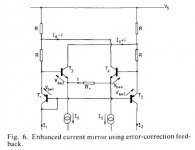
Jam, that patented circuit is very good indeed in simmed THD performance and in my sims works just as well as the combination circuit although I dont know sonically, I think it merits a try. I think Bobs critisism on this one is a bit unjustified although their might be other issues. The six transistor mirror, well thats getting a bit complex for a amp not to mention the next one you posted. I have some patented CM circuits too, using feedback and all other sorts of tricks but I didnt try them as I wouldnt use 10 to 15 trannys in a CM for audio amp.
Ostripper have you tried connecting the collector of the widlar helper transistor to the ltp current source instead. Will maybe not have audible effect but has measurement inprovement.
Sandyk I agree with you on the subjective benefit of balancing and that diode you use works to bring the ltp into balance but it could be even better with an improved CM like ostripper found out. Its questionable to chase THD figures but what the heck killing 2 ducks with one stone without much complexity. I dont think that in THD terms using only vertical diode with standard CM are going to help figures that much. One has to keep in mind that the improved CM if used alone not only betters the balance but it also raises among others impedance and gain leading to better THD figures. Thats why I tried the combination of widlar and 3 transistor wilson which is a big step up from standard CM.
Jam, that patented circuit is very good indeed in simmed THD performance and in my sims works just as well as the combination circuit although I dont know sonically, I think it merits a try. I think Bobs critisism on this one is a bit unjustified although their might be other issues. The six transistor mirror, well thats getting a bit complex for a amp not to mention the next one you posted. I have some patented CM circuits too, using feedback and all other sorts of tricks but I didnt try them as I wouldnt use 10 to 15 trannys in a CM for audio amp.
Ostripper have you tried connecting the collector of the widlar helper transistor to the ltp current source instead. Will maybe not have audible effect but has measurement inprovement.
homemodder,
That would be great if you can e-mail me the resulis but I would not mind waiting if you are going to post them.
I will have to try the patented circuit when I have a chance if it sims that good.
Regards,
Jam
That would be great if you can e-mail me the resulis but I would not mind waiting if you are going to post them.
I will have to try the patented circuit when I have a chance if it sims that good.
Regards,
Jam
Re: CM Discussion
That is the method used by Bob Cordell (in his old MOSFET Paper), as he pointed to by the concern of AndrewT.
Bob uses his Current Mirror in second stage differential instead
while so having equal loaded input LTP pair.
AndrewT is probably right in that a current mirror will disturb the balance at AC currents of the LTP pair.
Question is how much this disturbance means to the amplifier overall performance?
Another question:
Could we use a cascoding pair to 'hide' the LTP mirror
from the input pair's collectors?
sandyK said:"What about differential VAS? Or differential folded cascode "VAS"?
Instead of using current mirror loaded LTP, the differential VAS will bring balance in LTP transistors."
...
SandyK
That is the method used by Bob Cordell (in his old MOSFET Paper), as he pointed to by the concern of AndrewT.
Bob uses his Current Mirror in second stage differential instead
while so having equal loaded input LTP pair.
AndrewT is probably right in that a current mirror will disturb the balance at AC currents of the LTP pair.
Question is how much this disturbance means to the amplifier overall performance?
Another question:
Could we use a cascoding pair to 'hide' the LTP mirror
from the input pair's collectors?
Jam the 6 tranny cascoded wilson widlar is terrible, worse than all the others but I think the problem here is that they start oscilating, if stable the results could be different, this goes for the 4 transistor cascode as well. Do you know any circuits using this??
So far best results I had was that patent and my version of combining widlar and 3 transistor wilson. In all they are 4 tranny circuits and not to complex for audio amp use.
So far best results I had was that patent and my version of combining widlar and 3 transistor wilson. In all they are 4 tranny circuits and not to complex for audio amp use.
eerie sound
hello everone
Great thread.thanks to all.Is,nt Ostripper hearing Proper Stereo for the first time,If you wanted to sim the effect heard would,nt it have to be a kind of tolerence spread monte carlo on inter channel differences,phase may be.
just a noob thought.
regards
hello everone
Great thread.thanks to all.Is,nt Ostripper hearing Proper Stereo for the first time,If you wanted to sim the effect heard would,nt it have to be a kind of tolerence spread monte carlo on inter channel differences,phase may be.
just a noob thought.
regards
Re: Re: CM Discussion
The imprecision of the current mirror located in the differential VAS won't disturb sound as much as in the LTP.
As for the second question, should we be more concerned about voltage than current imbalance 😉 ?
lineup said:
...
Bob uses his Current Mirror in second stage differential instead
while so having equal loaded input LTP pair.
...
Another question:
Could we use a cascoding pair to 'hide' the LTP mirror
from the input pair's collectors?
The imprecision of the current mirror located in the differential VAS won't disturb sound as much as in the LTP.
As for the second question, should we be more concerned about voltage than current imbalance 😉 ?
homemodder,
I have not tried the six transistor current mirror looks way too daunting, when you say four transistor cascode do you mean the Widlar version? If so I have tried it but had problems with voltage swing and oscillations.
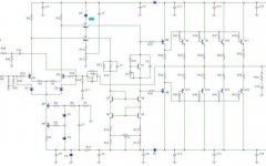
I like the four transistor Wilson which I have used in one of my amplifiers (see attachment)designs. This topology is also used in The AD844 and AD829 opamps. and works great on one end of a folded cascode.
I will have to try the patent version, we might be on to something here. When you say three transistor Wilson and Widlar do you mean a stantard Wilson with a cascode on the input side or a tree transistor Widlar with a cascode on the output side ( This works real well as it limits the heat generated on the output transistor hence reducing non-linearities this might be one of the reasons that the patent circuit works so well)?
Regards,
Jam
I have not tried the six transistor current mirror looks way too daunting, when you say four transistor cascode do you mean the Widlar version? If so I have tried it but had problems with voltage swing and oscillations.
I like the four transistor Wilson which I have used in one of my amplifiers (see attachment)designs. This topology is also used in The AD844 and AD829 opamps. and works great on one end of a folded cascode.
I will have to try the patent version, we might be on to something here. When you say three transistor Wilson and Widlar do you mean a stantard Wilson with a cascode on the input side or a tree transistor Widlar with a cascode on the output side ( This works real well as it limits the heat generated on the output transistor hence reducing non-linearities this might be one of the reasons that the patent circuit works so well)?
Regards,
Jam
Attachments
More stuff.................
http://techdoc.kvindesland.no/radio/psu/20061103161202293.pdf
fram Wireless World.
Jam
http://techdoc.kvindesland.no/radio/psu/20061103161202293.pdf
fram Wireless World.
Jam
Its the three transistor widlar with the cascode. If one takes the widlar helper tranny away you left with the 3 transistor wilson. This one and the patent circuit seem to be behave similar, as they present identical figures, the best of the lot. Seems no one has tried or used it before.
Maybe we can also have current source thread now to find better sources as this is another area where some improvement could be useful. Dr Bora tried to get some ideas and presented some in another thread but no one took the bait.
Maybe we can also have current source thread now to find better sources as this is another area where some improvement could be useful. Dr Bora tried to get some ideas and presented some in another thread but no one took the bait.
- Home
- Amplifiers
- Solid State
- Current Mirror Discussion