Schematics..
I'd love to have a look at the schematics. Which transistor types did you use to get that frequency response ?
I'd love to have a look at the schematics. Which transistor types did you use to get that frequency response ?
Schematics
OK, I see !
Seeing the schematic I understand how you got that performance. It looks a lot like current feedback opamp, implemented in discrete... I've wanted to try this but never got around to it.
So how does it sound ? Did you finish it yet ?
Keep up !
OK, I see !
Seeing the schematic I understand how you got that performance. It looks a lot like current feedback opamp, implemented in discrete... I've wanted to try this but never got around to it.
So how does it sound ? Did you finish it yet ?
Keep up !
The design is very basic, like the ones you can find in examples of current feedback amp theory, which is available on the net. The rest which I have added can be seen in integrated devices.
I will post results when it's finished. Meanwhile you can check my diamond buffer which has a very nice performace.
I will post results when it's finished. Meanwhile you can check my diamond buffer which has a very nice performace.
I have tested the amp now and it works, directly from simulation! Distortion seems lower in the real world. It's not significantly different from the soundcard 0.0088% and the soundcard alonde 0.0083% where hum is a part of this.
Step response is excellent. Risetime is much less than 75 ns which my signal generator has.
I haven't tested with my other signal source yet. 1 MHz square wave, 10 V pp is identical with the input signal. Offset only 3 mV out! The other channel has more but I haven't investigated why yet.
The sound is splendid
RightMark distortion analyze files are available, send me a message for the html files. File size around 1 MB.
hello!
hej peranders. vad skulle det kosta för mig att köpa ett sådant kretskort av dig ? är mycket intresserad av att skaffa mig en bra hörlursförstärkare 🙂
du kan nå mig på dannzig@home.se
hej peranders. vad skulle det kosta för mig att köpa ett sådant kretskort av dig ? är mycket intresserad av att skaffa mig en bra hörlursförstärkare 🙂
du kan nå mig på dannzig@home.se
Dann, personal questions is best if they are sent to me as a personal message. Besides only Fred knows swedish around here 😎
About your question, check my homepage!
About your question, check my homepage!
fred was actually "stand in" for the swedish cook in the muppets.........but mostly he was the drummer.....😀
peranders said:Besides only Fred knows swedish around here 😎
Hm, maybe you forgot a couple of others? Me for instance. 😉 😉
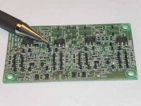
It's there and it's alive.jwb said:Nice looking circuit, p-a. But there is one pressing question! What happened to QRV-05?
It seems that not very many, except for Jocko, that have experince of current feedback amps, but I can really recommend it. In the weekend now I have listened to my speedmonster (compared to voltage feedback) and I simply like it. But I think I'm influenced by the looks of the amp. It feels right to touch it!
About simulation: I had a small ringing at a very high frequency, this without compensation cap. Only a very small capacitor removed this ringing. The simulation didn't take that!
About simulation: I had a small ringing at a very high frequency, this without compensation cap. Only a very small capacitor removed this ringing. The simulation didn't take that!
It looks like you have a single and dual channels. Is there any differences (other than # of channels)? Also, CFB amplifiers have lower high frequency distortion, but datasheets often lack distortion figures at low frequencies. Is the 0.0088% distortion across 20 - 20khz? Also, it's not clear: why does your technical data page indicate 0.002%?
Nice work Peranders and good that you share this with others.
JF
Nice work Peranders and good that you share this with others.
JF
The distortion figures must be taken for what they are. The are in the level of the soundcard and they are better because I had a litt bit hum also in the total signal. The distortion is measured at 1 kHz.
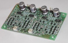
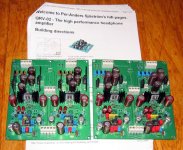
The pcb has two channels. The single channel one is only a diamond buffer.
Isn't rather clear that distortion at lower frequencies are the same or better than at high frequencies so there is no need really for those low frequency figures, altough it can be interesting.
The pcb has two channels. The single channel one is only a diamond buffer.
Isn't rather clear that distortion at lower frequencies are the same or better than at high frequencies so there is no need really for those low frequency figures, altough it can be interesting.
johnferrier said:Also, CFB amplifiers have lower high frequency distortion, but datasheets often lack distortion figures at low frequencies.
I have also noticced this lack of distorsion figures for high-speed
amps, both CFB and VFB actually. I suppose this is because
distorsion figures tend to be rather flat up to some frequency
where they start rising. Since these are very wideband
devices, the manufacturer probably see no point in using a
wider diagram than necessary just to show a long flat
distorsion spectrum up to this break point. Actually, we could
just as well ask why the low bandwidth ones have no
distorsion figures for the mHz and uHz range, but this is the
analogous case. Distorsion typically won't rise again at low
frequencies. Still, you are right in the sense that often the
diagrams don't quite show us if distorsion flattens out at
the low end of the digram or continue to decrease for lower
frequencies. Well, I suppose they don't expect anyone to
use these devices for such low frequencies as audio so they
might think nobody is interested in the distorsion figures for
lower frequencies.
Isn't rather natural to give figures which are interesting for the product. CFB opamps aren't made for audio, or at least intended for it, so why state "audio" figures?
I have now listened even more to the amp and I am really pleased the sound. Razorblade sharp impression, bass deep and firm, treble like a Sarek creek. I have also tested low omhish output and with 100 ohms. I'm amazed about the very very very small difference with original length of my headphone cable and Sennheiser HD545.
More should try current feedback. It's very easy to get working. I have used the classic topology topped with high speed technique from integrated current feedabck opamps. According to simulation it's very good to have cascodes in the diamond buffer. If not used you get a sharp peak at 10 MHz or so.
Sarek is a national park in Sweden, above the artic circle. Picture here:
http://ice.prohosting.com/sarekpa/
- Status
- Not open for further replies.
- Home
- Amplifiers
- Headphone Systems
- Current feedback high speed headphone amp with diamond output buffer