
Thin gray is the ideal non-distorted signal, thick gray is Class D amp output, red is the (open loop) distortion due to the dead time. But we diverge.
I understand the shift of the scene towards"digitale Modulationsverfahren" as a distraction from the core topic, namely the functional description of the progenitor Quad405.
So, what is current dumping?
"CD" is nothing more than a nickname for the different nature of the 405 compared to its competitors at the time. At the same time, Q9 is referred to as a dumper (an NPN transistor that only has to be switched on in the course of the time function to be amplified). This so-called dumper is an emitter follower that apparently works in operating class C.

TR9 = BDY77
is the main-DUMPER!
But, the real secret is hidden behind the SI diodes D5 & D6 (their differential resistance plays an important role in further understanding).
#
Q8 is also not uninteresting, perhaps more on this later - we want to distract (us) with the "Class D Amp" construction site.

So, what is current dumping?
"CD" is nothing more than a nickname for the different nature of the 405 compared to its competitors at the time. At the same time, Q9 is referred to as a dumper (an NPN transistor that only has to be switched on in the course of the time function to be amplified). This so-called dumper is an emitter follower that apparently works in operating class C.
TR9 = BDY77
is the main-DUMPER!
But, the real secret is hidden behind the SI diodes D5 & D6 (their differential resistance plays an important role in further understanding).
#
Q8 is also not uninteresting, perhaps more on this later - we want to distract (us) with the "Class D Amp" construction site.
Some preliminary remarks:
User wahab has made an interesting claim and tries to support his statement with indirect evidence (using TMC comparisons).
However, the actual formulation of the thesis is still missing, I will provide this thesis by proving the thesis myself. I don't yet know how far I will go, but I will keep it simple and figurative - linguistically packaged.
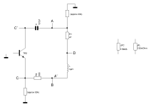
1) there is no bridge at all, the usual description reflects false facts.
2) there is no Miller loop, Miller's theorem and the transformation associated with it is somewhat different - personally, I can't do anything with the use of personal names. This should already make it clear that the "Miller-Ribbon" is nothing more than another nickname. As an analytically minded person, I have absolutely no use for the usual name juggling.
We are talking here about a local and frequency-dependent negative feedback, which is of course embedded in the global negative feedback via R2 (the 1k||1k resistor), i.e. quasi nested.
3)We are only interested in the small signal behavior, the signal zero crossing, so we also use all the transformations associated with the small signal model concept.
4)I will radically simplify it for the sake of tangibility (and so that it remains reasonably comprehensible to a non-specialist audience) and dispense with the correct engineering presentation.
On the whole, everything revolves around transformations and equivalents. The doping agent of every being of my species.
tpc
User wahab has made an interesting claim and tries to support his statement with indirect evidence (using TMC comparisons).
However, the actual formulation of the thesis is still missing, I will provide this thesis by proving the thesis myself. I don't yet know how far I will go, but I will keep it simple and figurative - linguistically packaged.
1) there is no bridge at all, the usual description reflects false facts.
2) there is no Miller loop, Miller's theorem and the transformation associated with it is somewhat different - personally, I can't do anything with the use of personal names. This should already make it clear that the "Miller-Ribbon" is nothing more than another nickname. As an analytically minded person, I have absolutely no use for the usual name juggling.
We are talking here about a local and frequency-dependent negative feedback, which is of course embedded in the global negative feedback via R2 (the 1k||1k resistor), i.e. quasi nested.
3)We are only interested in the small signal behavior, the signal zero crossing, so we also use all the transformations associated with the small signal model concept.
4)I will radically simplify it for the sake of tangibility (and so that it remains reasonably comprehensible to a non-specialist audience) and dispense with the correct engineering presentation.
On the whole, everything revolves around transformations and equivalents. The doping agent of every being of my species.
tpc
The complexity of the full circuit diagram obscures the simplicity of the current-dumping principle of operation.
John Linsley Hood in his "The Art of Linear Electronics" provides a good explanation, and a comparison with Technics Class AA, and Sandman's Class S designs.
I subscribed to Wireless World for many years, where Quad's circuit was thrashed out by many learned people in the Letters to the Editor.
They published critiques such as "Current Dumping - Does it Really Work?" by J. Vanderkooy and S. P. Lipshitz, published in Wireless World June 1978.
They published a critique of the critique by Doug Self in the letters pages in a following issue.
I get the impression that you are all criticising something you don't understand.
The complexity of the full circuit diagram obscures the simplicity of the current-dumping principle of operation.
That is absolutely correct!
And this is exactly what this concealment is about; the functional principle of the circuit is absolutely trivial.
I know that, I know all these little essays.John Linsley Hood in his "The Art of Linear Electronics" provides a good explanation, and a comparison with Technics Class AA, and Sandman's Class S designs.
Well, I don't know the letter to the editor from Douglas Self.I subscribed to Wireless World for many years, where Quad's circuit was thrashed out by many learned people in the Letters to the Editor.
They published critiques such as "Current Dumping - Does it Really Work?" by J. Vanderkooy and S. P. Lipshitz, published in Wireless World June 1978.
They published a critique of the critique by Doug Self in the letters pages in a following issue.
Hopefully you are referring to everyone else and not to me, because I have 100% understood the functional principle of the Quad405 circuit.I get the impression that you are all criticising something you don't understand.
It's all about the way it works and the real mechanism and not about the nominal construct CD.
By the way, I am not criticizing the QUAD series. It's all about wahab's claim, the thesis. And to show my colors, I am standing right by his side.
#
If one is committed to the idea of the CD, then in the case of the QUAD405 one can assume a maximum effective share of 6.244% (and this is viewed outside the significant frequency range of 0 to 7kHz).
PWM or PDMNothing digital going on there.. 😉
Is one of the elementary digital modulation methods. But, of course, you are absolutely right - there is no DIGITAL in the 405. Absolutely nothing is discretized here, neither in terms of time nor value, all is continuously and steadily.
tpc
I think a lot of people here could benefit from a real understanding of current dumping ...
https://www.quad-hifi.info/public/current+dumpng+article+p+walker+1976[1740].pdf
Jan
https://www.quad-hifi.info/public/current+dumpng+article+p+walker+1976[1740].pdf
Jan
Attachments
Last edited:

After this distraction, I have now lost the thread in my explanation of why Wahab is right.
🙁
But I'll find it again - guaranteed.
Preliminary information:
We make extensive use of transformations and also use the positive coupling called bootstrap in many different ways. There are C-CCS, but also V-CCS, etc.
But no bridge.
🙁
But I'll find it again - guaranteed.
Preliminary information:
We make extensive use of transformations and also use the positive coupling called bootstrap in many different ways. There are C-CCS, but also V-CCS, etc.
But no bridge.
Attachments
Thanks Jan,I think a lot of people here could benefit from a real understanding of current dumping ...
Jan
I personally love this great article too - but we've already remembered it several times in this thread.
🙂
greetings,
HBt.
The crucial point is that the entire output stage is a virtual member of the so-called Miller loop /Ribbon. And via R2 (R(fb)), as I already expressed with my phrase (everything is in the loop), everything is in the gnfb.
The key is precisely this apparent connection or the equivalent, we call this "virtual". The proof is very easy to provide in the simulation, just by looking at (for example) the THD, as the difference to the physical (real) contact with the node D and /or B. Since the difference is insignificant, the proclaimed miracle principle CD (as a bridge) cannot be responsible for the good THD. So no feedforward-take away error correction.
I'm starting to despair myself, but...
The key is precisely this apparent connection or the equivalent, we call this "virtual". The proof is very easy to provide in the simulation, just by looking at (for example) the THD, as the difference to the physical (real) contact with the node D and /or B. Since the difference is insignificant, the proclaimed miracle principle CD (as a bridge) cannot be responsible for the good THD. So no feedforward-take away error correction.
What exactly do you want to express with this, dear Jan?Yet, uninformed posts keep on popping up ...
I'm starting to despair myself, but...
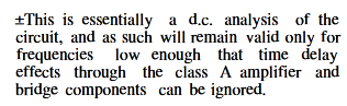
The ones who are uninformed are those who didnt really read the WW disclaimer thats state that their analysis hold
only at DC and then play the specialists while 15 years ago they didnt even know how exactly GNFB work in a 2 stage amp,
i once made a basic arithmetic demo on the subject and the same "informed" troll then aknowledged that he was cluless about each stage exact contribution to distorsion cancellation, seems that troll s memory is short.
Anyway here WW disclaimer.
Attachments
Last edited:
The way I understand CD is as follows. In a 'normal' amplifier with global nfb, the feedback factor is a constant (generally a resistive divider). The amount of feedback varies with open loop gain at the frequency of interest, so the distortion reduction also varies with loop gain at the frequency of interest.
That means that at cross-over, when the open loop gain varies wildly, the distortion reduction varies wildly leading to crossover distortion, especially with a class B stage with no bias current.
A CD amplifier has no (or very little) bias. If the dumpers start to conduct (or turn off), you would get massive xover distortion. But, due to the bridge, if the dumpers start to conduct, the current through the resistor in the dumper circuit causes the feedback factor to increase. The increase in loop gain due to dumper conduction is balanced by a decrease in gain from an increase in the feedback factor. In an ideal situation, the two would cancel and crossover distortion would be zero. In theory this could make the distortion zero, something that normal single loop feedback cannot, even in theory.
Jan
Last edited:
This thread started so well; I'm sure someone published a low-power version using an op-amp and current-dumper transistors, some 40 to 50 years ago.
I've had a few beers since then, so I can't remember the details, possibly in "Circuit Ideas", again in Wireless World.
I've had a few beers since then, so I can't remember the details, possibly in "Circuit Ideas", again in Wireless World.
The discussion thread is still intact and healthy.This thread started so well; I'm sure someone published a low-power version using an op-amp and current-dumper transistors, some 40 to 50 years ago.
kindly,
HBt.
Neither. As there is no quantisation, nothing digital can go on 😉PWM or PDM
Is one of the elementary digital modulation methods. ....snip
//
And this view needs to be reconsidered.The way I understand CD is as follows.
Absolutely correctIn a 'normal' amplifier with global nfb, the feedback factor is a constant (generally a resistive divider). The amount of feedback varies with open loop gain at the frequency of interest, so the distortion reduction also varies with loop gain at the frequency of interest.
Statically, this is the big mistake. To describe the signal zero crossing, we use the descriptive Wingspread Diagram, of course we work here with differential quotients, i.e. slopes ...That means that at cross-over, when the open loop gain varies wildly, the distortion reduction varies wildly leading to crossover distortion, especially with a class B stage with no bias current.
The OLG (the course) remains completely unaffected by all of this. A sufficiently large DC amplification ensures a (compensating) jump here. There is no gnfb (loop) for an infinitely small time span - if that is what you are trying to say, you are right.
Let's stay with the 405.A CD amplifier has no (or very little) bias.
No, there is a blend ..!If the dumpers start to conduct (or turn off), you would get massive xover distortion.
Indeed - there is no bridge ..!But, due to the bridge,
are fully at work (is a more meaningful formulation)if the dumpers start to conduct,
false conclusion!the current through the resistor in the dumper circuit causes the feedback factor to increase.
Which resistor do you mean specifically? R1=47Ohm or R2=500Ohm. The lower replacement Darlington transistor is initially completely in the race, a compoundBJT - if we only want to look at the lower BDY77 part, (then it is) it is optimally biased, i.e. class B according to Self's diction.
There is no increase - as mentioned, false conclusion. TR8 has (here) another task than just the usual view of a QC-OPS.The increase in loop gain due to dumper conduction is
Theoretically, fb & ffw systems can correct the remaining error to zero, which is why we like to speak of error correction. In practice, of course, this is impossible.balanced by a decrease in gain from an increase in the feedback factor. In an ideal situation, the two would cancel and crossover distortion would be zero. In theory this could make the distortion zero, something that normal single loop feedback cannot, even in theory.
Jan
kindly,
HBt.
Last edited:
Can we discuss this topic in person over a glass of beer please?Neither. As there is no quantisation, nothing digital can go on 😉
🙂
I'know what you mean.
- Home
- Amplifiers
- Solid State
- Current Dumping with OPAMP