A voltage amplifier wired as an integrator will not oscillate, it is stable with its dominant pole, and that could be called a Miller loop.
The gain falls with frequency, so the "current dumper" stage has an inductor, so its gain falls with frequency in a similar way.
Doug Self argued that many criticisms of the Quad amplifier circuit fail to mention loop stability.
The main advantage of the QUAD 405 is that it doesn't need someone employed on the production line to tweak a bias pot.
A resistor in series with a current source causes the measurable voltage at this resistor itself to become a voltage source with this resistance value as the internal resistance of the source.
This is why, for example, the working resistance of an (common) emitter circuit (practically, if rce ...) is also its output or internal resistance.
An ohmic resistor is therefore always also a current-voltage transformer.
But this is common basic knowledge.
tpc
This is why, for example, the working resistance of an (common) emitter circuit (practically, if rce ...) is also its output or internal resistance.
An ohmic resistor is therefore always also a current-voltage transformer.
But this is common basic knowledge.
tpc
In the first instance, the Quad405 is a tangled mess of control technology.The main advantage of the QUAD 405 ...
If we want to look at a straight amplifier in its sophisticated beauty, the Quad405 is a distorted chimera.
Sorry
😢
Sorry, @hbtaudio, handwaving instead of a clear proof of that Miller feedback loop won't work 🙂
But hey, it's almost Christmas. Let me offer a variation on the theme:

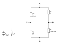
It is a concept of a composite amplifier similar to what John D. Yewen published in the Feb 1987 issue of Electronics & Wireless World, with Walker's feedforward correction added. The reasoning is that if U2 is slow, you can get maybe 60dB of loop gain at 20kHz. That may not be enough for a fantastic sound if U2 is not super linear, so it makes sense to add U3 to provide feedforward correction and cancel U2's distortion. I have not tried it in hardware, but in simulation it works well with some reasonably realistic models (and some important extra details, omitted here for clarity).
But hey, it's almost Christmas. Let me offer a variation on the theme:
It is a concept of a composite amplifier similar to what John D. Yewen published in the Feb 1987 issue of Electronics & Wireless World, with Walker's feedforward correction added. The reasoning is that if U2 is slow, you can get maybe 60dB of loop gain at 20kHz. That may not be enough for a fantastic sound if U2 is not super linear, so it makes sense to add U3 to provide feedforward correction and cancel U2's distortion. I have not tried it in hardware, but in simulation it works well with some reasonably realistic models (and some important extra details, omitted here for clarity).
Last edited:
I was already expecting you to throw in --->but the so-called Miller loop works perfectly, especially in the Quad405. And that's what it's all about, this loop.Sorry, @hbtaudio, handwaving instead of a clear proof of that Miller feedback loop won't work 🙂
#
I'm looking forward to your Christmas present, namely the correct (and complete) automatic-control modeling of the Quad405.
With this model (you know the extensive drawings of a classical control engineer) we will then prove that the Quad405 does not derive any benefit from the theoretical thought experiment (of faith) CD.
😉


To be honest, I don't like Christmas anymore.
greetings,
HBt.
The discipline is called "Regelungstechnik".
Next year (which is less than two weeks away), the Quad will be 50 years old. Although it still enjoys a loyal following, I think it is time to put it into the audio hall of fame, to stop second-guessing its creators and to create something new instead.
We have Class D now. No crossover distortion. Suitable fast MOSFETs didn't exist 50 years ago.Next year (which is less than two weeks away), the Quad will be 50 years old. Although it still enjoys a loyal following, I think it is time to put it into the audio hall of fame, to stop second-guessing its creators and to create something new instead.
Next year (which is less than two weeks away), the Quad will be 50 years old. Although it still enjoys a loyal following, I think it is time to put it into the audio hall of fame, to stop second-guessing its creators and to create something new instead.
That's about 20 years younger than the Lin configuration that most class-(A)B amplifiers are based on...
Including a Class D stage within a feedback loop is - er - problematic.Class D as a current dumper is a neat idea.
It doesn't need Current Dumpers because it already doesn't have crossover distortion and it already doesn't need adjustment.
Oh; and it is already efficient.
We have Class D now. No crossover distortion. Suitable fast MOSFETs didn't exist 50 years ago.
The dead zone also causes distortion in class-D amplifiers as far as I know. They can work well because their designers are not afraid to use high-order feedback loops with lots of loop gain.

Lin circuit published in Electronics September 1956.That's about 20 years younger than the Lin configuration that most class-(A)B amplifiers are based on...
QUAD 405 was introduced to customers in 1976.
The dead zone is on the high-frequency switching waveform, not on the audio waveform itself.The dead zone also causes distortion in class-D amplifiers as far as I know
That is true, but the dead zone does impact the accurate translation from analog audio to the PWM output, creating harmonic distortion.
Jan
Jan
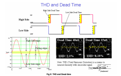
That drawing doesn't represent the 400kHz switching waveform.These are comparable and wear some ressemblance given the step by step nature of class D.
- Home
- Amplifiers
- Solid State
- Current Dumping with OPAMP