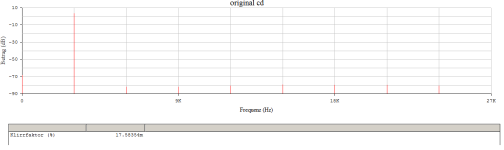
Let's take a look at what the current summation of the Current Dumper would theoretically be capable of.
RL = 8 Ohm
Dumper of 18 ohms & (virtually parallel to) 4.7 µH
Errorsignal is in this example only H3 (k3).

The famous THD1k = 0.03% !
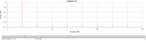
RL = 8 Ohm
Dumper of 18 ohms & (virtually parallel to) 4.7 µH
Errorsignal is in this example only H3 (k3).
The famous THD1k = 0.03% !
Geometric addition of phase-shifted currents ---> nothing more needs to be said about the concept. It can only work within very specific limits.
Whether the forefather Quad 404 really works is still being questioned today, I don't like its design at all - but does that automatically make me prejudiced? No, because only the measurement results of the real amplifier with a real and nasty load are relevant.
So it's the daily use, the listening use that counts and not exactly what's in the black box. The circuit of a quad is a bit sick, but how appealing it is too ...
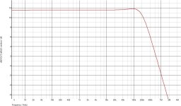
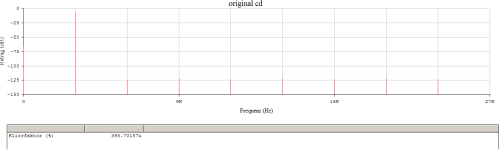
The corner frequency of 18 Ohm and 4.7 uH is about 600 kHz. It is not sufficient to correct a pure class B stage(no bias current).RL = 8 Ohm
Dumper of 18 ohms & (virtually parallel to) 4.7 µH
Quad 405 uses 47 Ohm with 3 uH. That is 2.5 MHz. That also means the unit loop-gain bandwidth of the amp itself is 2.5MHz. That was very brave back then.
PS, can blameless topology do 2.5MHz? Yes, if you do everything right, including trace routing and layout. Not with slow devices like 3055/2955 of course.
Last edited:

At first glance i thought that the BDY77 were the same kind of devices as the BDY56-58 wich have 10-30MHz Ft,
but actually these are high voltage versions of the early 2N3055 with a 800kHz Ft, in 1978 they replaced them
with 2SD554 wich are 3-5MHz, so it s unlikely that the first 405 could had a 2.5MHz ULG, in sims it s clear that
they limited the UG at 800kHz, the ULG being about 250kHz.
but actually these are high voltage versions of the early 2N3055 with a 800kHz Ft, in 1978 they replaced them
with 2SD554 wich are 3-5MHz, so it s unlikely that the first 405 could had a 2.5MHz ULG, in sims it s clear that
they limited the UG at 800kHz, the ULG being about 250kHz.
Attachments
Last edited:
It seems that the Quad405 dinosaur will haunt us for all eternity.so it s unlikely that the first 405 could had a 2.5MHz ULG, in sims it s clear that
they limited the UG at 800kHz, the ULG being about 250kHz.
😱
Give me the correct models and I'll simulate the thing up and down - additional analog analysis and deduction.
The thing is actually called error take off or iterative feedforward.
Attachments
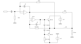
From the schematic from #83Give me the correct models and I'll simulate the thing up and down - additional analog analysis and deduction.
Feedforward, 47 Ohm
Inductor 3 uH
Feedback, 500 Ohm
Miller cap, 120 pf
If you remove opamp, Quad 405 is a single ended current feedback amplifier. It is not easy to model it with ideal opamp.I was actually thinking of the dinosaur called 405.
... that's why I asked for the correct PSPICE compatible models of the elements BJT.If you remove opamp, Quad 405 is a single ended current feedback amplifier. It is not easy to model it with ideal opamp.
But wahab has already explained that the original QUAD is nonsense - or have I misunderstood?
#
Here are a few quick results with the headphone version
NE5534 plus TL071 and PP 10mA Iq.
From 4Vpp the oven is off!
The NE5534 also lacks the power extension.
I use now
Feedforward, 47 Ohm
Inductor 3 uH
Feedback, 500 Ohm
Miller cap, 120 pf
Attachments
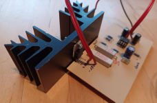
Why don't you try things out for yourself? With off-the-shelf power operational amplifiers, for example the TDA2030 or 2050.
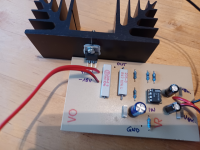
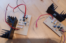
To liven things up, here's a picture of two modules from one of my collection boxes:
The bootstrap version called Class AA with a maximum of 9 watts into 8 ohms and the distortion of the LF356, i.e. no more than 0.005%. It's been a long time, 20 years already, oh dear, I'm getting old.
HBt.
🧙♂️
To liven things up, here's a picture of two modules from one of my collection boxes:
The bootstrap version called Class AA with a maximum of 9 watts into 8 ohms and the distortion of the LF356, i.e. no more than 0.005%. It's been a long time, 20 years already, oh dear, I'm getting old.
HBt.
🧙♂️
Attachments
I don’t have a spectrum/distortion analyzer. Even I build one, I cannot tell any difference with my ears. That’s why the most of my projects only stay in my simulation.Why don't you try things out for yourself?
It seems that the Quad405 dinosaur will haunt us for all eternity.
😱
Give me the correct models and I'll simulate the thing up and down - additional analog analysis and deduction.
The thing is actually called error take off or iterative feedforward.
I used the MJ15022 for the sims, whatever transistor will be good since the impulse response, and hence the transfer function,
is defined by the RC net 3.3k + 1nF at the IPS input as well as the miller cap, so even a 2N3055 pair is adequate,
and that s what they actualy used.
I always use OP-Amp. Models, in this case the original from Signetics.If you remove opamp, Quad 405 is a single ended current feedback amplifier. It is not easy to model it with ideal opamp.
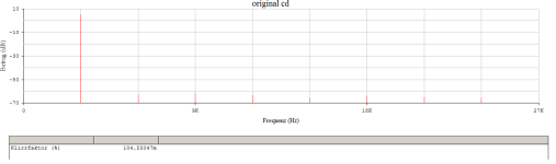
The headphone amplifier as a current dumper works perfectly with the NE5532. The error amplifier has an additional PP output stage that works 100% in A mode. The actual output stage, i.e. the second amplifier, is the part to be corrected - maximum THD3k below 500mWpk is 1m%.
regards,
HBt.
Psst
Whether this all makes sense remains to be seen.
Attachments
You have one too many 4148 diodes driving the the bases after the first opamp.
You probably wanted to point out that a diode and two emitter resistors are missing from the second operational amplifier part (the part that is actually faulty and needs to be corrected!). Correct? But then you immediately recognize the nonsense of the concept, which is not the intention. We want to play with our simulator and realize how fragile the adjustment of a functioning current dumper really is. A little bit of mismatch is enough to quickly turn 0.001% THD into 0.1%.
In theory, the dumper works perfectly, but unfortunately not in practice. Theoretically ingenious, practically a pain.
HBt.
Mr. M. Kühne
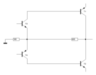
has obviously invested some practical time in the CD principle - and has arrived at the following result (which works in practice).

You could build on this if you want to build a largely alignment-free and currentless push-pull output stage. Of course, the complementary Darlington part is not completely currentless.
Bye,
HBt.
has obviously invested some practical time in the CD principle - and has arrived at the following result (which works in practice).
You could build on this if you want to build a largely alignment-free and currentless push-pull output stage. Of course, the complementary Darlington part is not completely currentless.
Bye,
HBt.
What does every QUAD405 and successor hide?
This is the question that arises after Mr. Kühne's efforts (the symmetries). Unintentionally, he has provided proof of the creativity of the original's circuitry and dimensioning tricks. To be honest, the original looks like a piece of handicraft.
I don't mean that in a derogatory way, because it also protects us( Mr. Walker and QUAD) from copycats /imitators and plagiarists.
#
What tolerance range is permissible for the elements Z1 to Z4?
This question is meant completely seriously, because today we are all in search of the “utopian THD” - and are no longer satisfied with 0.4% or 0.04%.
At the same time, our PowerAmp must be immune to any kind of naughty load (from the loudspeaker). Again, I mean this in all seriousness, because a real loudspeaker is not an ohmic resistor of 2, 4 or 8 ohms.
Current Dumper gives us a promise that it cannot keep. Or can it? If yes, then we should all (here in the forum) join forces to develop a corresponding output stage with up to 1kW peak at 2 static ohms.
Bye,
HBt.
Attachments
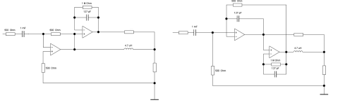
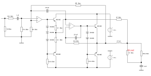
Following the modular principle, i.e. the Lego building blocks, we now add the so-called dumper: T5 and T6, the scenario already looks extraordinarily familiar to us.

We have already defined the amplification factor 1 + 50/18, as well as the bandwidth using the magic 500 Ohm resistor ..!
tpc /maybe
We have already defined the amplification factor 1 + 50/18, as well as the bandwidth using the magic 500 Ohm resistor ..!
tpc /maybe
To do current dumping, there are 2 major requirements or limitations.Current Dumper gives us a promise that it cannot keep. Or can it? If yes, then we should all (here in the forum) join forces to develop a corresponding output stage with up to 1kW peak at 2 static ohms.
1. It needs a very high gain and linear VAS. Quad uses a tripled Darlington configuration.
2. The class A stages has to provide at least around 1% of the total output current. If that is over 50mA,(1% of 100W into 8 Ohm), it is not practical to use VAS to drive the feedforward resistor directly. That means over that, you need create another low distortion class A (at least AB) stage to drive the feedforward resistor.
- Home
- Amplifiers
- Solid State
- Current Dumping with OPAMP